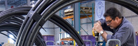
At MATCOR, we pride ourselves on being a world class manufacturer of unique cathodic protection systems and AC mitigation systems. Our anode systems offer you longer life, lower total installed cost, and are safer and easier to install than many conventional anode solutions. We have earned a reputation for exceptional manufacturing quality—but all companies say their products are world class and have exceptional quality, right? What makes MATCOR different? What does it mean to be exceptional?
At our state of the art Chalfont, Pennsylvania manufacturing facility we have developed a culture of quality. That is not to imply that we are perfect or that we don’t occasionally make a mistake; we are not perfect. However, we HAVE embraced, through our ISO Certified Quality Management System, a systematic approach towards excellence. So, while everyone aspires to do a quality job, our manufacturing team’s quality culture is based on perspiration—we work relentlessly to do a quality job for YOU by embracing the key tenets of quality.
Through our Manufacturing Quality Management System, we:
Document procedures for what we do
Train our team on the proper processes
Hold ourselves and our suppliers to high quality standards
Self-audit to ensure we are doing what we say we will do
Measure our performance daily through KPIs (key performance indicators)
Strive to continuously improve
Collect and act on YOUR feedback, comments and complaints
We’d love to hear from you about our manufacturing quality, please comment or contact us at the link below.
To get in touch with our team of cathodic protection experts for more information, to ask a question or get a quote, please click below. We will respond by phone or email within 24 hours. For immediate assistance, please call +1-215-348-2974.
MATCOR provides a full range of AC Mitigation capabilities including AC Modeling and Design engineering services, supply of our proprietary Mitigator® engineered AC grounding system, and an entire construction services organization capable of a wide range of AC Mitigation installation services. Two current projects highlight our construction service capabilities with regards to AC Mitigation. The first project involves several miles of zinc ribbon installation for an AC mitigation system in a congested suburban and urban environment using horizontal directional drilling (HDD) equipment. The second application is in a highly rocky environment in West Texas that requires the use of specialized rock trenching technology for zinc ribbon installation.
Zinc Ribbon Installation Using HDD in a Congested Environment
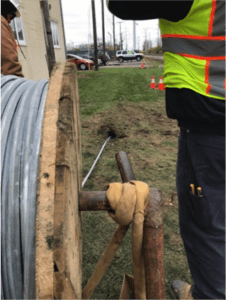
Figure 1 – Zinc ribbon being installed through HDD bore hole
This project in northwestern Ohio involved the zinc ribbon installation over several miles using one of MATCOR’s in-house horizontal directional drilling crews. The project required horizontal directional drilling to minimize surface disturbances due to the congested area.
With any typical AC Mitigation installation there are numerous precautions that must be taken to assure a safe installation. This starts with a thorough pre-construction safety review to develop the project site-specific health and safety plan. Each crew member participates in a daily safety meeting to review the day’s planned activities and address all safety concerns in advance of performing any work. Each crew member is required to have the appropriate operator qualifications and site-specific safety training as identified by MATCOR and the pipeline owner.
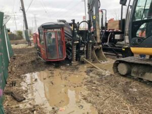
Figure 2 – HDD bore in process
Prior to any other construction activities, the first task is to perform a thorough line locating including potholing (excavation of the top of the pipe). This is to physically assure that the location of the pipeline(s) being mitigated is accurately marked to avoid any risks associated with construction activities in close proximity to the pipeline.
Once the pipeline has been physically located and properly flagged, each individual bore must be planned. The route of the bore is assessed prior to boring activities commencing. The bore planning includes:
Identifying entry and exit points
How the bore is to be tracked
Special precautions that might be needed to maintain the bore during the ribbon installations
How the cuttings will be captured, stored and removed
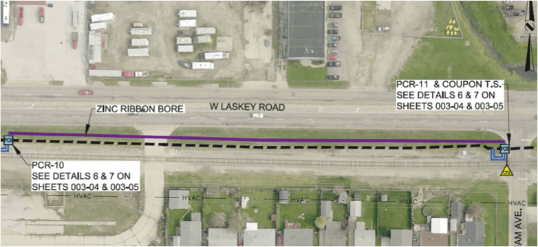
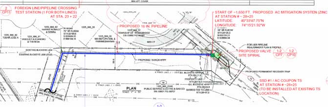
Figure 3 – Zinc Ribbon Bore – AC Mitigation design detail – note rail line to the South
As with any construction project, logistics and project management are key to the successful execution of the project. Working in conjunction with the owner and their designated project inspector to assure that the work is performed safely and in accordance with the AC Mitigation design requirements. For the project in Ohio, some additional complications included difficult weather conditions and working in close proximity to a railroad which requires additional permitting and coordination with the railroad. In some locations, traffic control was also required during the installation work.
Rocky Conditions in West Texas
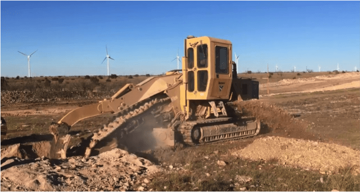
Figure 4 – Rock trenching in a difficult West Texas environment
Another project that MATCOR is currently completing involves the installation of approximately 15 miles of zinc ribbon in West Texas. The original installation plan called for the use of a cable plow to install the zinc ribbon mitigation wire; however, for large stretches of the installation, the rocky conditions forced MATCOR to switch from the planned cable plow to a high-powered rock trencher to cut through the difficult rocky terrain. This project illustrates the importance of using the right equipment to overcome difficult installation challenges. In some cases, being able to adapt to adverse conditions requires a change in construction methodologies and for this project, MATCOR’s ability to react and make equipment changes allowed the project to proceed on schedule with minimal customer impact.
This project also requires the use of HDD for one specific mitigation segment, as the pipeline traverses a cotton field which includes a buried drip irrigation system. The use of HDD is required to prevent any damage to the drip irrigation system during the AC Mitigation zinc ribbon installation. Coordinating the installation schedule around the cotton crop cultivation added another logistical challenge to the project.
Whatever your AC Mitigation challenge might be, MATCOR’s construction teams are able to work with our clients and their project needs to assure a safe and cost-effective installation project.
Have questions about zinc ribbon installation, or need a quote for AC mitigation materials or services? Contact us at the link below.
We’ve talked about AC Interference and we’ve talked about AC Modeling. The topic of our newest training video is AC Mitigation. The video is about 9 minutes long and we’ve included timeline indicators below so you can easily find your topic of interest in the video.
The goal for AC mitigation is to reduce your fault condition stress values to protect against stress coating damage and arcing potentials (arcing is less common because you need to be very close to the pipeline for arcs to appear). This includes:
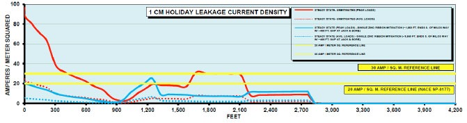
Reducing current density below your threshold value. Typically in the US we use 20 amps per meter squared for a one CM2
Maintaining AC step and touch potential below 15 volts so that people working in and around pipeline areas are not subject to shock due to a fault condition
AC Modeling Aids in Predicting Conditions [0:55]
We use AC modeling to provide predictions and look at the mitigated and unmitigated conditions. Some cases warrant building a model, in other cases we can use “ad hoc” methods (such as experience) to come up with an effective AC mitigation plan.
For our example pipeline application, AC modeling results show some locations to be concerned about where the 20 amps per square meter threshold is exceeded. These locations are indicated below, where the red line is above the yellow 20 amps per square meter reference line. What do we do to mitigate this risk?
In this case, we’re going to put in a gradient control line in the areas of concern next to the pipe. This is a grounding system that attaches to the pipeline so that AC being picked up by the pipeline has a place to go. The coating system is “too good” with only a few small holidays, which means all of the current being picked up tries to rush out of those few small holidays. This is how you end up with AC induced pipeline corrosion.
By putting in a grounding system at strategic locations along the pipeline, we can reduce the AC voltage being picked by discharging it and giving it a place to go.
There are several ways to design an AC mitigation system but they are all basically grounding systems. Our solution in this case is shown as the blue line representing a grounding mitigation line.
Typical AC Mitigation Strategies [2:23]
Install a gradient control mat at locations where people can touch the pipeline
Maintain safe pipeline to power line separation distances to avoid arcing problems during fault conditions
If separation distances are too close, include a shield that picks up current as it is dumped to the earth and deflects away to protect the pipeline
Provide grounding of the pipe to the earth to dissipate current being picked up during steady-state conditions
What is a gradient control mat? [3:00]
A gradient control mat is a simple device that is connected to the pipeline to protect workers from step and touch potentials.
It is connected to the pipeline appurtenance where a person can touch the pipeline, and extends out enough so that somebody standing on it will not have that step and touch potential. Since it is connected to the pipeline, the entire gradient control mat has the same potential as the pipe.
As soon as I step on to that gradient control mat, I don’t have a voltage difference between me and everything else. Even if I touch the pipe, the ground below me is at the same voltage as the pipe, so no current flows through my hand, to my body and into the ground.
It is a fairly significant effort to install a gradient control mat but they protect people close to that appurtenance. Once they are above that gradient control mat, touching or being near the pipeline is not going to cause a problem. Current doesn’t flow unless there is a voltage difference. You can actually be in an environment where there is high voltage all around you, and as long as you are at the same potential (or equipotential), there is not going to be any current flow, and current is what can injure or kill you.
AC Mitigation Case Study [4:33]
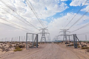
In the case study shown, a pipeline runs parallel for 8 km to a transmission line, with the towers next to the pipeline. In this case the towers are too close so we use a zinc ribbon shield wire to protect from fault conditions. The zinc ribbon picks up the current and dissipates it before it can cause damage to the pipeline.
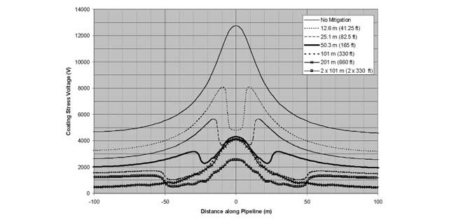
AC Mitigation Reduces Coating Stress Voltages
The chart below shows the effects without any mitigation, where you can see the voltage spike where it goes above 12000 volts of coating stress voltage.
You can see once various forms of mitigation are added, stress voltage drops below the limits. And depending on the type of coating, there’s a certain voltage limit that coating can withstand.
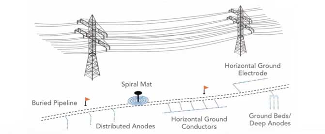
Pipeline Grounding Methods [5:46]
Spiral mat at pipeline valve stem location
Anodes in the earth that are connected to the pipeline; these become grounding rods for the pipeline
Horizontal ground conductors, connected at various lengths to the pipeline (gradient control line mitigation)
Deep anode ground beds
Deep Anode Case Study [6:25]
Deep anode ground beds are a little more expensive, however they a good solution in high resistance areas where you can’t discharge current into the ground effectively near the surface.
We did a project out west in the desert of the United States, where a new pipeline parallel to a transmission line was picking up AC voltage. In the very dry desert environment there was nowhere for this current to discharge. Grounding rods next to the pipeline do not work well in this case because the environment is so dry. We drilled holes 1000 feet into the earth and installed grounding cells. These were run up to the surface and connected to the pipeline to dissipate the AC voltage being picked up.
[7:11] There are a variety of ways to ground a pipeline; AC mitigation is basically how we ground the pipeline effectively.
AC Mitigation Materials [7:16]
The most common materials used for pipeline grounding include:
Zinc ribbon laid parallel to the pipeline
Bare copper, which is used predominantly in the corrosion industry
Engineered copper grounding systems; The MATCOR MITIGATOR® is an example of this type of system
Conducrete® systems where conductive concrete is used to enhance the earth’s surface area
AC Mitigation and Grounding Concerns [7:58]
Ease of installation
Performance
Life, how long is it going to last
Cost
Optimum AC mitigation [8:12]
The AC mitigation system is only as good as the modeling, so it is critical to ensure that modeling is accurate
Gradient control lines parallel to the pipeline are the most common grounding system used currently, although there are also quite a few locations using deep anode systems
For fault conditions, short lines at tower footings tend to be the most effective AC mitigation strategy
Have questions after viewing our AC mitigation video, or need a quote for AC mitigation materials or services? Contact us at the link below.
AC Modeling enables pipeline operators to evaluate and plan for mitigating AC corrosion.
There continues to be much greater awareness by pipeline owners and regulators of the adverse interactions (AC Interference) that can occur between buried pipelines and above ground high voltage AC transmission systems that share some parallelism in a common right of way. When AC Interference conditions exist, it is important that the potential impact is evaluated and when necessary mitigated. For many applications, the most cost-effective approach to assess and mitigate the impact of AC Interference is to use a complicated computer AC modeling program.
The term AC Modeling really covers multiple modeling evaluations, as an AC corridor can often be quite complex. They may include multiple HVAC transmission systems and multiple pipelines in a common corridor or multiple shared right of ways along a long length of pipeline. Each may require its own AC modeling. In addition, the modeling looks at several different risks assessing how the pipeline is affected by steady state AC induced current, the impact of fault current along the pipeline and an evaluation of the impact of a fault current on above ground appurtenances to assure safe operation in accordance with IEEE std. 80 step and touch potential criteria.
Thus, it is very important for any successful AC modeling effort that the modeling software be of an extremely high quality and capable of properly handling the complex interactions of these various networks. The engineer or technician developing the model must also have sufficient experience and expertise to properly configure and operate the model, and evaluate the results.
AC modeling involves four key phases:
Data Collection
Creating the Model
Establishing criteria
Evaluating mitigation strategies
Data Collection
The data collection is critical to a successful modeling effort (the old adage garbage in = garbage out is quite applicable for these projects). The data requirements can be broadly broken out into three categories:
The characteristics of the AC Transmission Line(s)
Physical geometry data on the tower including GPS location, height, # of AC circuits, tower configuration, height of each conductor, lowest point of each conductor, separation distance between conductors, shielding wire type and location, location of any phase transpositions, etc…
Electrical data on the Transmission Line(s), including peak and average AC Load (in each direction), fault current max and duration.
The characteristics of the Pipeline(s)
GPS location, depth of cover, coating type, coating resistance, pipeline diameter, pipeline wall thickness, location of all above ground appurtenances, location of all CP test stations and bonds to foreign structures.
The characteristics of the Environment
Detailed soil data at multiple depths along the length of the pipeline, location of any crossings, presence/location of any foreign CP Stations or other interference conditions.
Collecting all the appropriate data often requires some field studies and working with both the pipeline owner(s) and the transmission line operator to get the required data. In some cases, the modeler cannot get all the required information and must make an educated guess – the accuracy of which can affect the quality of the results.
Creating the Model
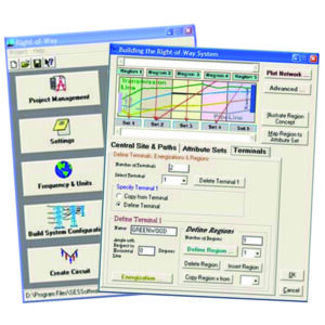
AC modeling software enables input of pipeline, transmission and environmental characteristics
Once all the data is collected, the modeler creates the model space, detailing all the pipelines and HVAC systems and providing the requisite parameters associated with each of these elements. There are several commercially available AC modeling software packages that each have their own format for inputting the pipeline, transmission and environmental characteristics. Once the model has been built, it can take hours, days and in some cases weeks, of processing time to run simulations and for the model to provide the results of the simulation.
Evaluating the Model Results Against Established Criteria
The results of the initial model run need to be evaluated against the criteria that is established by the pipeline owner. In the absence of specific guidance from the owner, MATCOR’s default criteria are:
No more than 20 A/m2 AC current density for mitigating AC corrosion during steady state induced AC current
3000 volts maximum coating stress during fault conditions for newer FBE type coated pipelines in accordance with NACE standard SP0177-2014
15 VAC for step and touch potentials at above ground appurtenances
For any given application, one or more of these criteria may be exceeded along the model’s area of analysis.
Adding AC Mitigation and Reevaluating the Modeling Results
Once the initial unmitigated results have been evaluated against the criteria that has been established, the modeler then adds, based on their experience with these systems, a mitigation scheme to the model with grounding at selected locations. This is often an iterative project where the model is run and the results evaluated and then if necessary, additional mitigation can be added or excess mitigation can be removed and the model rerun again in search of an “optimized” modeling solution that addresses all of the threats and results in meeting the requisite criteria.
Final Report
Once the AC modeling effort has developed a solution, the modeler develops a final report. Typical components of a final report include an introduction detailing the scope of the study, graphical illustrations of the pipeline(s) and transmission line(s) overlaid onto a satellite image, description of the modeling software used, detailed graphs/charts showing the results of the modeling, detailed drawings and bill of materials for the AC mitigation solution being recommended and appendices with the underlaying data.
Summary
AC Interference issues can be quite complex and modeling often offers the only valid way to assess and mitigate the risks from AC faults and steady state induced currents. When considering AC modeling it is important to look at the model being used and the modeler performing the evaluation.
Learn about our AC modeling and mitigation solutions:
 At MATCOR, we pride ourselves on being a world class manufacturer of unique cathodic protection systems and AC mitigation systems. Our anode systems offer you longer life, lower total installed cost, and are safer and easier to install than many conventional anode solutions. We have earned a reputation for exceptional manufacturing quality—but all companies say their products are world class and have exceptional quality, right? What makes MATCOR different? What does it mean to be exceptional?