One of the specialty groups in the BrandSafway Specialty Services Division is Diamond Thermal Systems (DTS), an esteemed leader in reliability and safety. DTS specializes in the evaluation, repair, and long-term care of heat trace systems.
DTS offers customized services to evaluate risks, identify vulnerabilities, and offer comprehensive heat tracing solutions.
What is Heat Tracing?
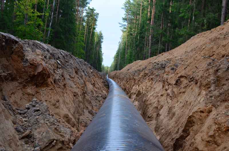
Heat tracing maintains consistent processing temperatures and protects pipelines and equipment from the adverse effects of cold environments. It is a reliable solution in industrial settings where precise temperature control is crucial for operational efficiency and equipment integrity.
Heat tracing is crucial for safeguarding assets and maximizing productivity across various industries, including oil and gas, chemical plants, and power generation.
The Importance of Heat Trace System Audits
Conducting thorough heat trace audits is the best defense against winter freeze-ups. It reduces the need for costly emergency repairs and promotes proactive system reliability.
DTS heat trace audits comprehensively delve into the critical components of your heat trace system:
Power Distribution Panels
Power Junction Boxes and Heat Trace Cables
Insulation Systems
Post-audit, you’ll receive a comprehensive report detailing system insights, accompanied by visual documentation, findings, and actionable recommendations. Moreover, we provide transparent pricing for turnkey services encompassing heat tracing, insulation, and scaffold services required for any necessary repairs.
Supporting All Heat Trace Systems
At DTS, we proudly support all heat trace systems, regardless of the original equipment manufacturer (OEM). Our commitment to excellence means that irrespective of your system’s specifications, we possess the expertise and resources to deliver optimal solutions.
Additional Resources
The presentation below was recently presented to a large power plant operations team; however, the material presented is equally applicable to our oil and gas upstream and midstream clients.
Your MATCOR representative can help put you in touch with the right contacts at our sister company, DTS, should you have any questions or are looking for heat tracing help.
To get in touch with our team of experts for more information, to ask a question, or to get a quote, please click below. We will respond by phone or email within 24 hours. For immediate assistance, please call +1-215-348-2974.
In a recent MATCOR blog post, we discussed exothermic welding and pin brazing: Cathodic Protection Pipeline Connections: Exothermic Welding vs. Pin Brazing.
While the article focused on informing, we briefly discussed safety: “both methods are safe procedures when trained personnel follow the correct procedures.” This article will take a deeper dive into the safety considerations and procedures around making connections to pipelines using exothermic welding and pin brazing technologies.
Trained Personnel
Only trained personnel with sufficient experience should make connections to a pipeline. Therefore, short-service and inexperienced personnel should only perform this work if doing so under the direct supervision of an experienced person.
Daily Tailgate Safety Meeting
Note: Different organizations use different terminology, but the basic process is the same.
Every day the team plans and reviews various site activities. At this meeting, they review all applicable instructions, and identify, discuss, and document all potential safety hazards. Each team member signs the document to verify that they understand all safety concerns and their responsibilities.
Safety Hazards
Because pipeline connections are thermal, potential safety issues include flash, burns, accidental ignition, pipe burn-through, pipeline damage, inhalation risks (dust, smoke, ignition product, etc.), and eye injuries.
Therefore, safe entry conditions must exist before team members enter a pipeline or other structure excavation site.
Proper PPE
Personal Protective Equipment (PPE) is non-negotiable when performing pipeline connection work. All team members must:
Wear a hard hat and face shield to protect their head and face.
Wear safety glasses under their face shield with a 5.0 shade rating for pin brazing to protect the eyes.
Wear a particulate mask to protect yourself from grinding dust entering the lungs. Additional breathing protection equipment may be required to protect against inhalation of welding fumes in poorly ventilated areas.
Wear fire-resistant clothing to protect the torso, arms, and legs.
Wear leather gloves free of flammable or thin material to protect the hands.
Wear safety-toed leather boots (no rubber, neoprene, or other flammable materials) to protect the feet.
Positive Identification of the Pipeline
Before any physical work such as excavation, coating removal, heating, grinding, or welding on a pipeline or other structure, the project owner should approve the proposed work and work methods. This step includes positive identification of the pipeline or other asset(s) by the owner or owner’s representative.
Air Monitoring
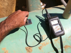
It is critical to monitor the air at the work site both initially and continually during the work with an LEL gas sensor.
Before proceeding, also test all flanged fittings and valves within 25 feet of the pipeline connection location should be tested with the gas sensor.
Thickness Measurement
Another critical safety step is for trained personnel to test the ultrasonic thickness of the area to be welded. The goal of this testing is to confirm that adequate wall thickness is present to prevent weld “burn-through.”
The table below details the minimum steel wall thicknesses as recommended by ERICO.
Record all results and compare them to nominal wall thickness. If the results indicate possible wall loss due to internal corrosion, the team must not proceed with exothermal welding.
Note: Do not perform exothermic welding if you measure a difference of 20% or more from nominal thickness or readings below 0.110” are measured.
Nominal Pipe Size
Schedule
Wall Thickness
0.5″
40
0.109″
0.75″
40
0.113″
1-2″
10
0.109″
2.5-4″
10
0.112″
5-10″
5
0.109″
10+”
5
> 0.109″
Coating Removal and Surface Profiling
Before coating removal, the pipeline operator should confirm that the coating is asbestos-free. Alternative removal procedures and safety precautions are required if the coating contains asbestos. A face shield should be used whenever grinding activities are performed.
Additional Considerations and Precautions
Explosive Internal Conditions
For active gas and liquids pipelines, the fluid velocity and lack of oxygen prevent the internal fluid from igniting due to the temperature rise in the pipeline wall. However, out-of-service lines are likely not fully purged, and oxygen and vapor may ignite inside the pipeline or vessel; purge these lines before proceeding.
Only perform exothermic welding on standard-thickness steel piping or vessels. Aluminum, copper, and thin-walled steel pose a greater risk of burn-through.
Don’t use anything larger than a 15-gram charge when welding onto steel fuel piping or vessels. Other structures, such as ductile iron pipes, may be more tolerant of more significant weld charges.
As you can see, both methods of pipeline connections are safe. However, adequately trained and experienced people must use the proper procedures and take the appropriate precautions.
To get in touch with our team of cathodic protection and AC mitigation experts for more information, to ask a question, or get a quote, please click below. We will respond by phone or email within 24 hours. For immediate assistance, please call +1-215-348-2974.
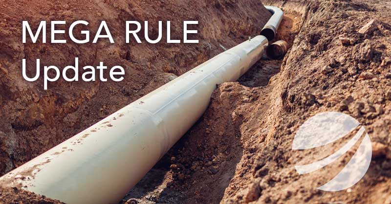
Recently PHMSA issued its final rule expanding Federal pipeline safety oversight to all onshore gas gathering pipelines. Known as the PHMSA Mega Rule, this ruling has tremendous impact on the US pipeline industry, adding significant scope to the current pipeline integrity management requirements.
The final rule affects tens of thousands of miles of previously unregulated gas gathering pipelines. Also, pipeline operators have to report safety information for more than 450,000 miles of gas gathering lines governed by Federal reporting requirements.
Some of the impacts of the PHMSA MEGA rule on the industry include:
An approximately 20% increase in the number of regulated pipelines in the United States The addition of 20% more regulated pipelines had a significant impact on an industry where highly qualified integrity professionals and related services were limited in supply and the industry was already struggling to meet demand. These additional pipelines required significant integrity resources.
Expedited reporting requirements The time restrictions for implementing the new rule were accelerated, with initial reporting requirements having started in July 2020. The time to comply with these regulations was reduced by 20% from the initial draft order timeline.
Increased cathodic protection requirements Many pipelines that previously were not regulated and have not had proper CP required a properly designed, maintained, and tested cathodic protection system.
What Does The Final Rule State?
The final rule expands PHMSA’s Part 192 to gas gathering lines that fall within Class C, a new pipe category. Within Class C, the requirements for operators vary based on a risk scale. The risk scale varies with pipeline diameter and proximity to people (BIHO – buildings intended for human occupancy).
For pipelines that meet these criteria, the requirements for corrosion control (CFR 49 Part 192 Subpart I – Requirements for Corrosion Control) will now apply to these previously unregulated lines. The Part 191 incident and annual reporting requirements have expanded to include all previously uncontrolled gas gathering lines, regardless of Class.
How Can MATCOR Help Company Operators Comply with PHMSA Mega Rule?
Gas producers and midstream gas pipeline operators have to reevaluate their pipeline networks to incorporate any previously uncontrolled pipelines to comply with CFR 191 and CF 192. MATCOR offers a wide range of cathodic protection and integrity services to help our customers including:
If you are looking for help complying with the PHMSA’s new Mega Rule and its additional requirements, please contact us. We will respond by phone or email within 24 hours. For immediate assistance, please call +1-215-348-2974.
AC mitigation is the process of designing and applying pipeline grounding systems to:
Prevent voltage spikes during fault conditions
Reduce AC current density to protect against AC-induced corrosion
Maintain AC step and touch potentials below 15 Vac to protect personnel from shock hazards
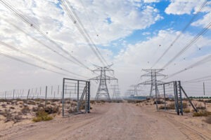
Pipelines that parallel overhead high-voltage AC transmission power systems are subject to AC interference. AC interference has several potential adverse impacts on the safety of personnel and pipeline integrity. Assuming that these conditions exist, there are several measures that can be taken to mitigate the AC interference present in a pipeline. These AC mitigation strategies are detailed in various international standards including two AMPP (formerly NACE) standard practices: SP0177-2014 Mitigation of Alternating Current and Lightning Effects on Metallic Structures and Corrosion Control Systems, which primarily focus on safety for operators and other people working on or near pipelines subject to AC current and lightning events, and SP21424-2018. This addresses the guidelines and procedures for risk assessment, mitigation, and monitoring of AC-induced corrosion on pipelines.
There are four basic approaches to mitigating AC Interference. These mitigation strategies are:
1. Fault Shielding
One of the primary concerns with high-voltage AC transmission systems parallel to buried pipelines is the risk that a fault condition at a transmission tower could result in the rapid discharge of fault current near the pipeline. This could lead to direct current arcing in soil – rare but very damaging. More common is the rapid ground potential rise that subjects the pipeline coating to large voltage gradients that result in coating damage. Fault shielding is a suitably designed grounding system that is installed between the tower footing and the pipeline that acts to shield the pipeline and shunt harmful currents away from the pipeline by providing a low resistance path to earth. This typically takes the form of a parallel shielding wire, either copper or zinc, connected to the pipeline.
2. Gradient Control Mats
When high levels of AC voltage are present on a pipeline, either during a fault condition or as the result of an inductive coupling during normal steady-state operations, personnel in close proximity to and/or touching any above ground or exposed appurtenance are at risk for electrical shock step or touch hazards. Installing a gradient control mat, which is a system of buried bare conductors, typically galvanized steel, copper, or zinc, connected to the structure, provides localized touch and step voltage protection by creating an equipotential area around the appurtenance.
3. Lumped Grounding Systems
Lumped pipeline grounding systems consist of shallow or deep localized grounding conductors that are connected to the structure at strategic locations to reduce the AC voltage level along the pipeline. This provides protection to the structure during steady-state or fault conditions from the nearby electric transmissions.
4. Gradient Control Wire
Gradient control wire grounding systems function the same as the lumped grounding system. With this type of system, long continuous grounding conductor(s) are installed horizontally and parallel to the pipeline. They are strategically located and sized to reduce the AC-induced voltage along the pipeline during steady-state or fault conditions from the nearby electric transmission.
For mitigating high levels of AC-induced voltage along a pipeline, gradient control wires are the most common form of AC mitigation. Hybrid systems that combine lumped grounding systems with gradient control wires are also common. Regardless of the type of pipeline grounding system used, all of these AC mitigation approaches involve installing a grounding device to the affected structure to allow AC-induced current and fault current to be quickly discharged off of the pipeline.
AC Modeling
Prior to installing an AC mitigation system, it is common to use complex AC modeling software to evaluate the impact of fault currents and estimate the steady state induced currents that can be expected along the pipeline. This information is used to determine the quantity and location of mitigation required based on numerous factors, including the resistivity of the soil, the physical characteristics of the pipeline, the operating parameters of the HVAC transmission system and the spatial distances between them.
Engineered AC Mitigation Systems
Based on a thorough assessment of the pipeline and high voltage AC transmission system interaction, including modeling results when available, an AC mitigation system is designed by experienced engineers familiar with the mitigation strategies detailed above. This engineered AC mitigation system would detail the quantity and location of grounding installations required for a specific application. MATCOR’s MITIGATOR is an example of this type of AC mitigation system.
Other features of an engineered AC Mitigation system include:
Special Backfill
It is quite common to install the grounding conductor in a special backfill material. The purpose of the backfill can vary depending on the conductor material chosen and the type of backfill used. The benefits of various types of AC mitigation backfill include:
Enhanced surface area – conductive backfills such as carbon or conductive concrete are used to effectively increase the surface area of the grounding conductor reducing the overall resistance to earth.
Corrosion/Passivation Protection – some backfills are designed to protect the grounding conductor from corrosion or passivation of the conductor that could adversely affect the life or impede the performance of the grounding conductor.
Hydroscopicity – some hygroscopic backfills readily attract and retain water from the environment, helping to maintain a low uniform resistance around the grounding conductor.
Solid State Decouplers
These devices are almost always used in conjunction with AC mitigation systems and are usually installed wherever the grounding system is connected to the pipeline. These devices are designed to allow AC current to flow off the pipeline during steady-state or fault conditions while blocking all DC current. This effectively isolates the pipeline’s cathodic protection (CP) system from the AC mitigation system, preventing the mitigation system’s grounding conductors from taking CP current from the pipeline.
AC and DC Coupons and Remote Monitoring Test Stations
Regardless of which mitigation strategies are being used, it is important to
design and install a monitoring system to be able to affirm compliance with the AC Mitigation criteria established in SP21424-2018. This includes monitoring both AC and DC current densities. The monitoring system should be designed to collect representative data at regular and continuous intervals. This usually includes remote monitoring of AC corrosion criteria.
MATCOR provides complete AC Mitigation solutions including design, supply of materials, turnkey installations, and comprehensive testing services.
If you are looking for help with AC Mitigation systems or services, please contact us. We will respond by phone or email within 24 hours. For immediate assistance, please call +1-215-348-2974.
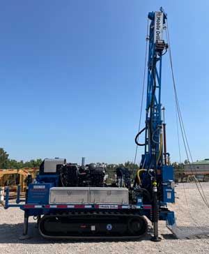
MATCOR is excited to announce the acquisition of a new drill rig to our existing fleet of HDD and vertical drill rigs.
Our newest rig is designed to be a cost-effective option for drilling shallow holes. The rig features a much smaller footprint than the conventional deep anode drill rigs used for installing Durammo® and other deep anode systems.
Drill Rig Features
The smaller and more agile auger rig allows MATCOR to be able to maneuver the rig in tighter areas than the full-scale vertical rig would allow. Additionally, the unit is available with a hollow stem drill pipe allowing us to lower anodes in place in environments where an open hole may not be feasible. The rig is capable of drilling holes down to 100 feet deep, but for hollow stem purposes, we are limited to a depth of only 50 feet.
What This Means for Our Future
MATCOR is excited to add this new rig to our industry-leading inventory of cathodic protection installation enabling us to better compete for:
Shallow conventional anode beds
Distributive anode beds around tanks and congested facilities
Mobility is increased since it is loaded on to a semi-trailer
For more information, please contact us at the link below, or reach out to your local MATCOR account manager.
This article explores the answer to a question posed by a student about the length of pipeline protected by a cathodic protection system.
We recently received a question from our website from someone who self-identified as a Student. We love when people ask technical questions and are pleased that students visit the MATCOR website–we have always strived to have a content-rich website to help share CP knowledge. The question is as follows:
“For installed impressed current CP systems with 15 anodes, what would be the approximate radius/length of a 200-mile petroleum metal pipe that would be protected?”
So before diving into the answer, let’s frame this question with an assumption, identify some unknowns and provide a definition.
Assumption
The 15 anodes are part of a single anode bed. The anodes are electrically remote from the pipeline and connect to an appropriately-sized DC power supply (transformer/rectifier, solar power/battery unit, thermoelectric generator, etc.)
Unknown #1: Pipeline Details
Before doing any detailed engineering, there are a few details that must be specified:
Pipeline diameter and material of construction
Coating type and condition
The layout of the pipeline (location of pumping stations, valve stations, and metering stations)
Unknown #2: Soil Conditions
Understanding soil resistivity in terms of location, frequency, and spacing, is critical when designing cathodic protection systems for long-length pipelines.
Definition of Attenuation
a lessening in amount, force, magnitude, or value according to Merriam-Webster
When discussing at what distance cathodic protection continues to be effective along a pipeline, you must consider the attenuation of the CP current. At some point, the current diminishes along the length of the pipeline, becomes insufficient, and can no longer protect the pipeline.
The Answer: Impressed Current CP Systems are Complicated
We can effectively use attenuation calculations for signals generated on a uniform conductor and transmitted through a uniform environment.
In this case, the pipeline is not a uniform conductor; unless it is bare, it is anything but uniform. The coating has less than perfect effectiveness and an unknown number of defects distributed in an unknown manner. The environment is equally non-uniform; soil resistivities change based on location and weather changes. The more non-uniformity, the more inaccurate the results will be for any attenuation calculations.
It is virtually impossible to model mathematically for older pipelines with insufficient coatings. The only effective strategy is to collect data by installing a temporary current source to measure the effective current throw in each direction in multiple locations along the pipeline.
For new pipelines with very good coatings, it is possible to perform some attenuation calculations and empirically determine a reasonable separation distance between anode stations.
The math starts with determining something called the propagation or attenuation constant. To calculate this, take the square root of the resistance per unit length of the structure divided by the leakage conductance per unit length.
In Simple Words…
How hard is it for the current to travel along the pipeline versus how easy it is for the current to jump onto the pipeline?
The smaller this number, the further current will spread. Key factors affecting the attenuation constant include earth resistivity (higher resistivity soils mean further current spread) and coating quality (better coating means further current spread). Armed with this, there are six simultaneous equations that we can use, and that include hyperbolic sine and cosine functions.
Larger, new construction pipeline projects require you to consult with a professional engineer. A brief newsletter article will not adequately cover the mathematical gymnastics involved. We did say that the math is complex.
Well-coated, newer pipelines in moderate to high-resistivity soils can typically be protected for 20+ miles in each direction from an anode bed. Poorly-coated or bare pipelines in low-resistivity soils may require anodes every quarter mile or less.
Need more information? Please contact us at the link below.
This article explores a deep anode system gone wrong and guidelines for properly sizing the system coke column.
Earlier this year, we received a call from a pipeline customer with whom we have a solid relationship.
Historically, they used graphite anodes for their deep anode installations. But over the past few years, they began trying the MATCOR Durammo® Deep anode System with success.
When one of their new Durammo anode installations started having strange operating data, it was time to get MATCOR on the phone pronto and figure things out.
MATCOR reviewed the RMU operating data on the wayward installation and found that the data was indeed strange.
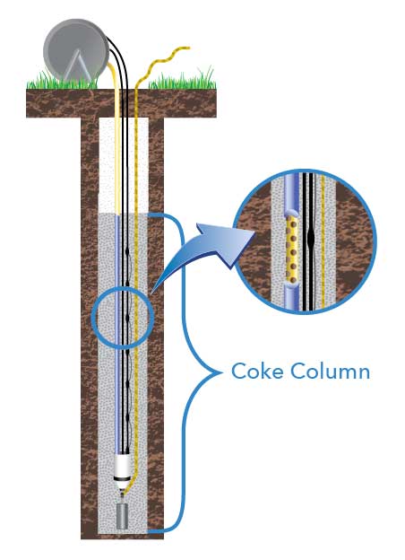
The DC output oscillated from periods of robust DC current output to periods of no discernible DC output. We also looked at the deep anode system design and noted the rather short coke column height. The height was only 100 ft of active anode in an 8-inch column. We sent a technician to the site to investigate.
First, we checked the installation and operation of the remote monitoring unit (RMU). Was a poor RMU connection causing intermittent good/bad data? This was not the case.
Next, we checked the continuity of the two anode lead cables. The Durammo® system has a top lead cable and a bottom lead cable. These two cables should be electrically continuous. In this installation, they checked out properly.
Finally, we checked the vent pipe for obvious issues.
Having confirmed that the spurious data was not the result of a poor RMU connection and that the anode system cabling appeared to be intact, we began to suspect that the problem was in the coke column and its immediate environment.
The Culprit? A Small Coke Column.
When we investigated further, we determined that the on-again, off-again readings could be the result of excessive gas generation into a rather small coke column. Both phenomena are heavily impacted by the anode system’s coke column to earth current density.
When the anode system generates more gas than can be exhausted through the vent pipe and diffused through the surrounding earth, gas molecules begin to accumulate between the column particles and at the anode to coke and coke column to earth interfaces. Gas is not electrically conductive, and with enough trapped gas in the column, the system resistance can quickly rise to a point that the anode system cannot overcome this resistance, and the current output drops quickly.
A short-term solution is to turn off the anode system for a period, allowing the gas to disperse inside the coke column and the system should return to normal operation. At least until the gas molecules build up again to block the anode system.
Coke Column to Earth Interface Current Density: The Magic Number
The magic number often cited for anode coke column to earth interface current density is 150mA/ft2. Anything above this number might cause problems. Below this number, history shows that the impact of gas blockage and drying out are generally minimal.
In our example, a 100 ft coke column with an 8-inch diameter hole means that any current output above 31 amps would be pushing that 150mA/f2 threshold.
The 150mA/ft2 current density assumes a high-quality, properly installed coke. This forms a well-compacted column that promotes electronic conduction and limits electrolytic conduction. A well-formed coke column is critical for anode systems using mixed metal oxide anodes, since MMO anodes have an inherently smaller surface area available to be in contact with the column.
It is unclear why the cp system designer recommended a short anode active length for this anode system – other than perhaps the cost saving of using less coke backfill.
While a shorter column does have a positive cost impact, the performance can become an issue, as was the case with this installation. Ultimately, this customer is planning a new Durammo® anode installation for this location with a significantly longer active area.
Need information or a quote for MATCOR deep anode systems? Please contact us at the link below.
Rusty chats with Dean Lioliou, MATCOR Strategic Account Manager and AMPP Central Area Chairman
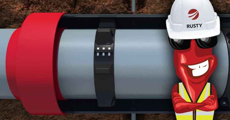
Rusty: Dean, thanks for taking a few minutes to discuss the application of VCI for cased pipeline crossings. First, what is a cased crossing?
Dean: Cased pipeline crossings are a common feature in the industry. They are used primarily at road and rail crossings.
The casing (also referred to as the encasement pipe) is a larger diameter pipe that is designed to take the loading from vehicle or train traffic on the road and absorb/deflect that loading from the carrier pipeline inside the casing.
In addition to the encasement pipe and the carrier pipe there are other key elements to a case crossing. Notably, there are non-metallic spacers that position the carrier pipe inside the encasement pipe, and dielectric end seals that prevent the ingress of water and soil. Finally, there are vent pipes on each end of the casing. These provide a warning and route product to a safe location in the event of a pipeline leak inside the sealed casing.
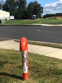
Pipeline Casing Vents on each side of a road crossing in Chalfont, PA
There are tens of thousands of these cased pipeline crossings throughout the United States.
Rusty: So, what are the corrosion challenges with cased crossings? What can go wrong?
Dean: Pipeline operators have found that an inordinate amount of pipeline leaks occur at cased crossings. Therefore, operators are actively looking to eliminate these whenever possible.
It is important to evaluate existing casings periodically. Two mechanisms can adversely affect pipeline integrity at cased crossing locations.
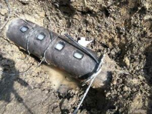
The first is a metallic short. This results from the carrier pipe shifting inside the encasement pipe. It causes a direct metallic contact between the carrier pipe and the encasement pipe.
Shorted casings can significantly impact the cathodic protection system protecting the pipeline. This is due to the encasement pipe drawing CP current away from the carrier pipe. Shorted casings also increase the risk of AC Interference, AC induced corrosion and shock hazards at the above ground vents.
The second casing failure mechanism is related to the integrity of the end seals over time. In many cases, these end seals develop leaks allowing water and soil into the space between the carrier pipe and the encasement pipe. This creates an electrolytic couple. The introduction of these contaminants can lead to accelerated rates of corrosion of the carrier pipe.
Rusty: What are my options if my casing is shorted or the carrier pipe exhibits signs of corrosion?
Dean: You can employ several strategies to address corrosion concerns with cased pipeline crossings:
Excavate ($$$). With this first approach, you dig up the casing and either remove it entirely or repair it. Repairing involves exposing one or both ends to repair the end seals and if necessary, readjust the spacers to clear the shorted condition. This is a construction intensive operation but, in many cases, can restore the cased crossing to an as-new condition.
Fill with Wax ($$). A second approach is to fill the annular space with a high di-electric wax. There are a variety of wax treatment options available. Typically, the wax is introduced through the vents and every effort is made to fill the entire annular space with the wax material.
The wax acts much like a coating covering the carrier pipe and prevents corrosion like a coating system. The industry has found that this is not always a complete solution, since voids in the wax fill can allow pockets of corrosion.
Fill with VCI ($). The third approach is to pump the annular space full of an aqueous gel or powder, or a slurry formulation of corrosion inhibitor material. The corrosion inhibitor is typically a combination of volatile corrosion inhibitor (VCI) and soluble corrosion inhibitor (SCI) that combine to stop corrosion. This method has received industry and regulatory approvals over the past decade and is gaining market share as operators become familiar with the technology and its advantages.
Rusty – How challenging is it to fill a pipeline casing with wax or with VCI?
Dean – Both operations are similar in many respects.
For both wax and VCI filling installations, repairing the existing casing is often the first step. You inspect the end seals and spacers, and where appropriate, remove and replace them.
The interior space between the carrier piping and the casing is flushed clean of dirt and other debris. Once the repairs are complete and the ends are sealed, you calculate the volume of product needed to completely fill the space between the carrier pipe and the casing.
Then the product is prepared according to the manufacturer’s recommendations. Pumping or filling the space is different for each of the type of fill, but both technologies require appropriate equipment and experienced installers.
Wax fills typically use a heated wax product for larger casings. Cold flowing wax can be used on some smaller casings.
For wax fill applications, the space between the carrier pipe and the casings must be completely flushed and cleared out during the repairing of the end seals.
Even with a well-prepared casing, achieving a complete wax fill is very difficult. Voids and gaps are typical.
One published study of 143 wax filled casings found that the average fill was 81%.
For VCI installation plans, the appropriate vapor corrosion inhibitor types and delivery methods are an important considerations. The VCI slurry needs to be mixed properly before being pumped into the casing using the appropriate pumping equipment.
Because VCI applications typically use an aqueous slurry with an experienced installer, VCI is easier to install than a similar wax application. The VCI component is designed to release from the aqueous solution after being pumped into the casing to fill all vapor spaces. Therefore, concerns over gaps and voids are non-existent.
Rusty – What about concerns with bacteria in the space between the carrier pipe and the casing?
Dean – This is an area where the two fill types differ significantly.
For wax filled casings the goal is to completely fill the space with wax displacing or encapsulating any bacteria. However as noted above, areas of incomplete fill or voids in the wax encapsulation can leave space for bacteria to continue to grow.
With VCI, the VCI chemistry increases the pH (9 to 9.5 is typical) inside the casing. This range makes it very difficult for bacteria to grow, while also neutralizing any acid secretions from the bacteria.
Rusty – Can Cathodic Protection help with protecting carrier pipes inside filled casings?
Dean – With wax filled casings, the wax has a high dielectric value and does not allow cathodic protection current to pass.
This prevents the carrier pipe and casing from draining cathodic protection current from the pipeline CP system, but it also provides no protection to the carrier pipe. The VCI gel that sets up is conductive and allows cathodic protection current flow. Some evidence supports the benefit of cathodic protection and VCI working in tandem to prevent corrosion.
Rusty – How can pipeline operators monitor the effectiveness of any cased crossing corrosion solution?
Dean – Most pipelines can be assessed using In Line Inspection (ILI). These pipelines can use smart tools with MFL, and other tools, to assess and monitor corrosion in the carrier pipe with a casing.
For wax filled casings, if ILI is not an option, there are no other good monitoring options. For pipelines that cannot be inspected using smart pig technology, conventional above ground pipeline testing technology is limited.
For VCI filled casings, we employ various technologies in conjunction with VCI including coupons, ER Probes and /or UT probes installed between the carrier pipe and the pipeline casing, to monitor the effectiveness of the VCI in the casing. These are installed and connected to RMUs for remote monitoring, or wired to a local junction box for direct reads during surveys.
Rusty – Any final comments Dean on Cased Pipeline Crossings?
Dean – Cased crossings are a challenge for pipeline owners.
Should you have any additional questions, please reach out to a MATCOR account representative for more information. As a full-service corrosion company, we have extensive experience and a wide range of capabilities including both wax and VCI installations for casings.
Have questions or need a quote for corrosion prevention materials or services? Contact us at the link below. For immediate assistance, please call +1-215-348-2974.
Rusty and Josh Johnston chat about a recent project and case study involving the use of linear anodes for hard to reach places.
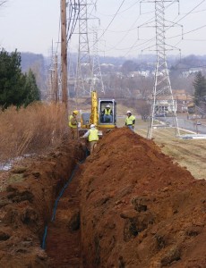
This month, MATCOR exhibited at the AMPP Central Area Conference held in Kansas City. MATCOR’s Mr. Josh Johnston, along with Mr. Chad Farris of Energy Transfer, jointly presented a paper—a case story using linear anodes as a shallow horizontal anode bed installed along two pipelines in central Kansas.
Rusty: Josh, tell us how it felt to finally be in a real-life conference interacting with people in person after the last year and half of cancelled conferences and virtual conferences.
Josh: It is always great to get to interact with our friends and industry colleagues, clients, suppliers and competitors to share information and discuss the challenges that our industry faces—especially given the events of the past couple of years. Presenting this paper was a great opportunity to highlight the use of linear anodes to protect hard to reach areas on older pipelines.
Rusty: Can you describe the problem that you covered in your presentation?
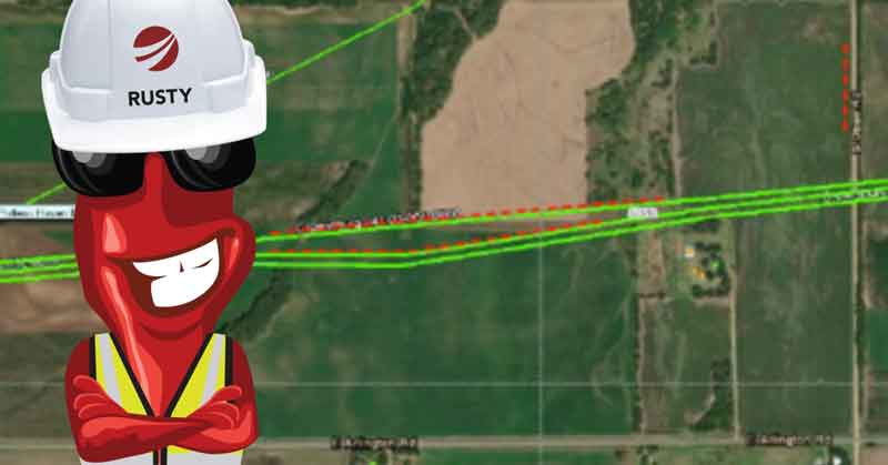
Josh: Energy Transfer had two older pipelines that were not meeting criteria in a rural location. As is typical in a lot of pipeline cathodic protection applications, the pipelines were being protected by impressed current anodes located at road crossings where power was readily available. The roads ran parallel to each other and were located one mile apart. The pipeline traversed these two roads and the area in between was mostly farmland. As a result of the age and coating condition, the shallow horizontal anode beds, located at the road crossings, were not able to project much more than a ¼ mile from each end, leaving approximately ½ mile in the center under protected. This was clearly identifiable in the close interval survey (CIS) data.
Rusty: Couldn’t they simply increase the current output of the existing shallow ground beds at each end of the pipeline to drive more current to the center section in between?
Josh: They tried that approach, and it did not work, raising concerns that driving excessive current onto these older pipelines could actually make the situation worse by further disbanding any coating close to the existing ground beds.
Rusty: So where did MATCOR come into this project
Josh: MATCOR proposed linear anodes be installed parallel to each of the pipelines in the area between the two roads. MATCOR developed the very first MMO (mixed metal oxide) linear anodes over 30 years ago and we have the most experience designing linear anode CP systems.
Rusty: So it sounds easy, you take a couple of ½ mile segments of linear anode, trench them in parallel to pipeline and run a couple of long extension cord cables back to the road where there is power.
Josh: Well it does sound easy; however, in practice it is critical that any linear anode design carefully addresses voltage drop, and that the power feed cabling is configured so that each anode segment output is balanced. If this is not engineered properly, you could have a large disparity in the voltage being applied on one end of the anode segment relative to the other end. This would result in a very uneven distribution of current. Discussing the design considerations for the power feed cabling was the primary focus of this presentation.
Rusty: So how did it work out?
Josh: MATCOR was able to use some creative cabling analysis and routing to assure that the voltage difference from one end of an anode segment to the other was no more than a 10% variance. The post installation and commissioning CIS data delivered an outstanding current distribution.
Rusty: Thanks for providing a very quick overview of your presentation—any final thoughts or comments?
Josh: When designed properly, linear anodes can be a real problem-solving solution for older pipelines with current distribution and attenuation issues.
Have questions or need a quote for linear anodes or installations services? Contact us at the link below. For immediate assistance, please call +1-215-348-2974.
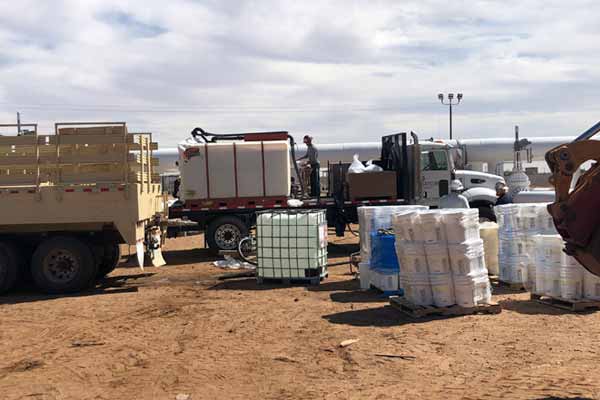
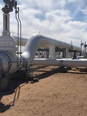
MATCOR recently completed a significant pipeline preservation project at a newly constructed pipeline station in West Texas. The project involved injecting Zerust Vapor Corrosion Inhibitor into multiple above ground pipeline manifolds to prevent internal corrosion. The rest of the pipeline remains under construction.
Using vapor corrosion inhibitors (VCI) to protect internal pipeline surfaces is an established technology proven very effective for pipelines post hydrotest.
Typically, all pressure-containing piping requires hydrotesting once the piping fabrication is complete. This ensures that there are no faulty welds and that the piping system can handle the design pressure without any leakages.
This fitness for service testing, unfortunately, introduces water and possibly bacteria into the piping. After the hydrotest is completed, and the water is drained, there remains residual moisture (and potentially bacteria) that can prove very corrosive even with efforts to dry the internal surfaces.
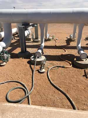
For pipeline preservation applications, the VCI chemical is typically mixed with water into a slurry. Then, it is pumped into the piping manifolds using a series of injection pumps and injection ports through hoses from multiple mixing tanks.
How Does VCI Prevent Pipeline Internal Corrosion?
The VCI molecules diffuse and adsorb to the surface, forming a very thin (molecular level thin) protective layer that blocks water and oxygen from reacting with the internal metallic surface of the piping. The molecular level VCI barrier, when properly applied, can last for months and even years as the balance of the pipeline construction is completed.
For this project in West Texas, MATCOR prepared and installed over 24,000 gallons of VCI Solution inside the piping manifolds after their fabrication and testing. Because of the above ground nature of the project, we added methanol (anti-freeze) to the VCI slurry mixture to provide freeze protection for the winter months.
In addition to pipeline preservation projects, VCI is a great product for tanks and pipeline casings.
To get in touch with our team of cathodic protection experts for more information, to ask a question or get a quote, please click below. We will respond by phone or email within 24 hours. For immediate assistance, please call +1-215-348-2974.