Cathodic Protection—What is it and how does it work?
Cathodic protection (CP) is a corrosion prevention technique used to protect metal structures buried in soil or submerged in water. By turning the structure into the cathode of an electrochemical cell, CP stops corrosion before it starts.
Common applications include pipelines, storage tanks, offshore platforms, and other critical infrastructure exposed to corrosive environments.
Table of Contents
What is Cathodic Protection?
Corrosion is a natural electrochemical reaction that occurs when metals are exposed to moisture, oxygen, and other elements in the environment. Over time, this causes metals to oxidize, deteriorate, and fail.
Cathodic protection is a proven electrochemical method used to prevent corrosion of metal surfaces. It works by redirecting corrosion currents away from the protected structure, ensuring long-term durability and safety.
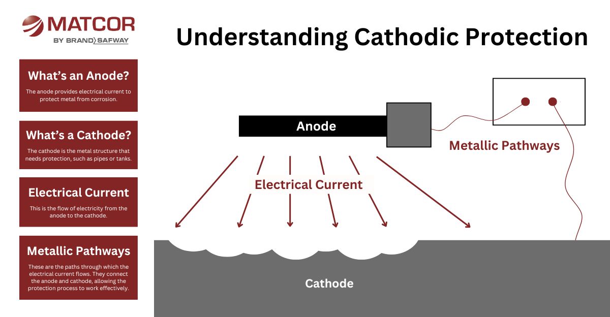
How Does Cathodic Protection Work?
Corrosion occurs when metal is exposed to moisture and oxygen, forming an electrochemical reaction. CP interrupts this process by applying an alternative current path.
There are two types of cathodic protection:
- Galvanic (Sacrificial Anode) Systems: A more reactive metal (like zinc or magnesium) corrodes instead of the protected structure. Ideal for small systems with low current requirements.
- Impressed Current Cathodic Protection (ICCP): An external power source supplies a steady current to durable anodes, offering long-term protection for large structures like pipelines, tanks, and marine assets.
Proper design ensures the current flows to the right areas, effectively halting corrosion.
Want to learn more? Watch Ted Huck’s Introduction to Cathodic Protection on YouTube (300K+ views)!
Primary Cathodic Protection Methods
While this page focuses on the principles of cathodic protection, you can explore our engineered cathodic protection systems for specific configurations and hardware solutions:
- Deep anode systems
- Linear anodes
- Tank bottom protection
- Custom CP system design
- And more!
Cost Considerations
The cost of cathodic protection depends on several factors:
- Size and complexity of the structure
- Environmental conditions (soil resistivity, moisture, salinity)
- Chosen method (galvanic vs. ICCP)
- Installation and maintenance needs
Galvanic systems are typically more affordable upfront but are suited to smaller applications. ICCP systems require higher initial investment but offer extended service life and lower long-term maintenance costs.
Industries That Use Cathodic Protection
Cathodic protection is critical across many sectors:
- Oil and Gas – Pipelines, well casings, and storage tanks
- Water and Wastewater – Treatment plants, water mains, reservoirs
- Power and Utilities – Power plants, substations, grounding systems
- Marine and Offshore – Docks, piers, offshore platforms
- Infrastructure – Bridges, airports, and buried metallic assets
While cathodic protection is a universal solution, its application for midstream assets is unique; for a deeper look at industry-specific strategies, see our comprehensive pipeline corrosion protection guide.

Why Choose MATCOR for Cathodic Protection?
With more than 50 years of experience, MATCOR is a global leader in cathodic protection.
- Turnkey design, installation, and maintenance
- Patented anode technologies for enhanced performance
- In-house engineering, field services, and manufacturing
- Compliance expertise for regulated industries
- Global reach with local service
FAQs—Cathodic Protection Explained
Get beyond the basics with the answers to the most common questions we hear. Have a question not answered here? Ask our experts!
Protect your assets for the long-term. Contact MATCOR today for a custom CP system tailored to your project needs!
An anode is a primary component in cathodic protection systems. It functions as the source of electrons and discharges DC current. The anodes is more negative relative to the protected structure.
The cathodically protected structure is the cathode in a CP system. It is where current flows after it discharges from the anode. The cathode is more positive relative to the protected structure. As electrons flow to the cathode, it polarizes, or becomes more electrically negative.
An electrolyte, for cathodic protection purposes, is an environment around the cathode (protected structure) that is electrically conductive enough to allow current to flow from the anode to the cathode. In addition, the anode and cathode must both be in this environment enabling cathodic protection current to flow from the anode to the cathode. In some cases, there might be multiple electrolyte layers or types through which the current might flow.
Buried or submerged structures require or can benefit from the proper application of cathodic protection. Assets commonly protected utilizing CP, for example, include oil and gas steel pipelines, steel and ductile iron water piping systems, tank bottoms on large diameter above ground storage tanks, ductile iron fire hydrant risers, and HVAC transmission tower guide wire anchors. Marine near-shore structures, such as steel pilings and sheet pile walls, ships and other large vessels, are some additional examples of cathodically protected assets. These are some common CP applications, but there are numerous others.
When cathodic protection current flows from the anode to the protected structure (the cathode in the circuit), the structure’s electrical potential will shift more electrically negative. This is typically measured in mV. We call this shift in potential polarization. Polarization is a measure of cathodic protection current effectiveness. Once the polarization is sufficient, we deem the structure cathodically protected. Important to realize, is that the time it takes to fully polarize a structure can vary. It depends on the structure and its environment. In some cases a structure can take weeks to fully polarize.
When cathodic protection current stops flowing from the anode to the protected structure, the structure begins to depolarize. The rate of depolarization can vary depending on the structure and its environment.
There are two basic criteria per NACE International standards you can use to confirm that a structure is cathodically protected. 100mV of polarization is the first criteria. This simple criteria entails the following: first, you measure the potential of the structure without any CP applied (native potential). Then, after you apply cathodic protection long enough to achieve polarization, measure the potential again. If the potential difference is greater than 100 mV, the structure is protected. This is commonly known as the 100 mV shift criteria. The other criteria is the 850 mV Off potential criteria. In this case, a native potential baseline is not necessary. This criteria simply requires that the potential of the structure be more negative than -850 mV after accounting for all current sources (by turning them off for an instant).
Instant off is the process of taking measurements the instant you turn off power to an impressed current CP system. When you have multiple current sources, you must turn them off simultaneously using synchronized interrupters. The purpose of turning all the current sources off is to eliminate the IR drops in the circuit. As current (I) flows through cabling there is a resistance (R) that the current must overcome – this is known as voltage drop because V=I x R.
When attempting to measure the level of polarization, it is important to eliminate the IR drops in the circuit that are the result of current flow creating these IR drops. By instantaneously turning the current off, the IR drop readings immediately reduce to zero because the current (I) is now zero. This means that the polarization you measure immediately after turning off the current is the true polarization current. Timing is critical because with the current turned off the structure will immediately depolarize. The polarization potential will begin to decay. The goal of instant off polarization readings is to catch the polarization level as you turn power off and before the depolarization process begins.
CIS or close interval survey, internationally more commonly referred to as CIPS (close interval potential survey), is a common means of validating the proper performance of a cathodic protection system along long length pipelines or within stations/plant piping networks. The survey consists of taking potential readings as the crew walks over the center of the buried pipeline. We usually take these readings while cycling on and off all influencing current sources at a regular intervals. Thus, readings capture the potential between the pipe and a reference electrode. We capture both the current on and current off cycle readings. This process repeats over the entire length of the pipeline. We then analyze the on/off data to confirm the CP system is working properly and achieving the required system polarization.
You can always contact MATCOR of course, however ScienceDirect topics include many books and peer reviewed journals on the subject of CP.
Have a question not answered here?
We will reply to your question via email and post it here.
To get in touch with our team of cathodic protection experts for more information, to ask a question or get a quote, please click below. We will respond by phone or email within 24 hours. For immediate assistance, please call +1-215-348-2974.
Contact a Corrosion Expert


