Cathodic Protection Systems Designed for Long-Term Corrosion Prevention
MATCOR cathodic protection (CP) systems are engineered solutions that stop corrosion before it starts. For a complete, end-to-end solution—from design through installation and testing—our turnkey cathodic protection solutions deliver consistent performance and streamlined project execution.
Each system is manufactured in the USA at our ISO 9001:2015-certified facility and built to meet the most demanding project specifications.
Learn more about cathodic protection.

Customized Design for Every Project
MATCOR’s experienced engineering team creates custom cathodic protection designs based on:
- Soil resistivity and environmental factors
- Structure size and coating condition
- Design life requirements
- Access and installation considerations
We also design and install cathodic protection ground beds using advanced anode materials and backfills to ensure optimal current distribution and long-term performance.
See how our CP systems perform in the field.
Built to Industry Standards
All MATCOR cathodic protection systems are engineered to meet applicable industry and regulatory standards, including:
- AMPP SP0169 (formerly RP0169) – Control of External Corrosion on Underground or Submerged Metallic Piping Systems
- DOT 49 CFR Part 192/195 – Pipeline safety for gas and hazardous liquids
- API 651 – CP for aboveground storage tanks
- Project-specific standards and client specifications
System Monitoring & Maintenance
Proper maintenance ensures your cathodic protection system continues to perform as designed and remains in compliance with regulatory standards. MATCOR offers expert support for system health and troubleshooting, including:
- Annual Surveys and Compliance Testing – Annual evaluations ensure your system performs reliably and remains compliant with AMPP, DOT, and project-specific standards.
- System Troubleshooting and Repairs – On-site diagnostics and corrective action for underperforming or damaged systems.
- Remote Monitoring – MATCOR offers remote monitoring solutions for new or existing systems using RMUs, providing visibility into system performance without requiring site visits.
Cathodic Protection System Applications
A cathodic protection system uses direct current to counteract the natural corrosion process in metal structures such as pipelines, storage tanks, or steel-reinforced concrete. By converting the protected structure into the cathode of an electrochemical cell, the system prevents it from losing electrons—and therefore from corroding.
Cathodic protection systems are commonly used for:
- Pipeline cathodic protection
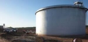
- Underground storage tanks
- Above-ground storage tanks (ASTs)
- Steel-in-concrete applications
- Marine structures
Types of Cathodic Protection Systems
We offer two primary types of CP systems, depending on your application:
Our Galvanic (Sacrificial) Anode Systems provide a cost-effective, low-maintenance solution for smaller structures and coated pipelines where external power is unavailable. MATCOR designs these systems for maximum efficiency and simple installation.
For large scale and high-resistivity environments, MATCOR’s Impressed Current Cathodic Protection Systems (ICCP) deliver precise, high-output current control. We engineer robust deep anode and linear anode configurations to ensure uniform coverage and extended asset life.
Key Components of a Cathodic Protection System
Effective CP systems rely on specialized components that work together to provide reliable protection and enable easy monitoring and adjustment:
- Anodes – Sacrificial (magnesium, zinc, aluminum) or impressed current (mixed metal oxide, graphite, etc.)
- Power Source – Rectifiers or solar-powered units for ICCP systems
- Ground Beds – Deep or distributed configurations to improve current distribution
- Reference Electrodes – Measure potential and ensure the system is working as intended
- Test Stations – Allow for regular system monitoring and compliance testing
- Backfill & Cabling – Materials ensure efficient current flow and long-term durability—even in harsh environments.
Explore Our CP Solutions
With over 50 years of experience, MATCOR delivers full-scope cathodic protection systems—custom-designed, field-proven, and backed by unmatched corrosion expertise.
Explore our full range of cathodic protection systems, components, and field services.
FAQs—Cathodic Protection Systems Explained
Anodes can be broken down into two basic anode types – galvanic anodes (frequently referred to as sacrificial anodes) and impressed current anodes. Galvanic anodes use the natural voltage differential between the anode and the structure to drive current off the anode and to the structure. On the other hand, impressed current anodes use an external power supply to drive current off the anode and to the structure.
Galvanic anodes are basically metal castings that do not utilize an external power supply to drive current. They rely on the natural potential differences between the two metals to drive the cathodic protection current. There are three primary types of galvanic anodes. Magnesium is the most active type of galvanic anode and is used primarily in soil applications. Comparatively, Zinc galvanic anodes are less active and commonly used in low resistivity soils and brackish water. Zinc is also the primary metal in galvanized applications. Finally, seawater applications typically use the third type of galvanic anodes, aluminum.
NOTE: People often refer to galvanic anodes as sacrificial anodes because the CP reaction consumes them. This is also true for many impressed current anodes. The term sacrificial implies that a power supply does not exist, and that the anodes utilized are more active than the protected structure.
There are two major advantages of galvanic anode systems. Firstly, they do not require a power supply. In addition, in many applications the cost of providing power and installing a power supply can be quite significant. Second, since there is no power supply, they require virtually no regular maintenance. As a result, in the right applications, these two benefits make galvanic anode systems cost effective.
Galvanic cathodic protection systems come with three considerable limitations. Firstly, they have Limited power. The driving force between the anode and the structure is limited to around 1V maximum, and frequently much less than 1V driving force. Therefore, larger structures often require more current than what can economically be provided by galvanic anodes. Secondly, they have limited life. Galvanic anodes consume at relatively large rates in terms of several kg/amp year. As a result, this significantly limits the anode life in some applications. Thirdly, the offer limited control. Galvanic anodes have no power supply, so we cannot adjust the output by varying the power applied to the anode. Galvanic anode systems operate solely based on the system resistance, relying on the voltage differential between the anode and structure.
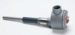
Impressed current anodes discharge current when powered by an external DC power source. Typically, this external source is a transformer/rectifier that converts AC power to DC power. With enough external power supply units, impressed current anode systems can discharge enough current to protect virtually any structure. This is regardless of size or coating status. We do not need to choose these anodes based on their activity level. We can instead choose them based on their current discharge characteristics – how much current can they handle. The three most common impressed current anodes are graphite, high silicon cast iron, and electro catalytic type anodes.
There are two basic classes of anodes. Anodes that electro-chemically react to generate the electrical current flow includes magnesium, zinc and aluminum as well as graphite and high silicon cast iron impressed current anodes. These anodes consume at a defined rate based on the generated current. We can define their consumption rate in terms of kgs of mass consumed for every so many amp-years of operation. There is always a consideration for utilization of the anode. You can never fully consume 100% of the anode mass. At some point, the anode degradation impacts the anode’s ability to perform. So, it is quite possible for these electro-chemically reactive anodes to calculate the expected anode life.
The second class of anodes are electro-catalytic. They are not a reactant but promote electro-chemical reactions. These catalytic type anodes are either platinum based or MMO type. MMO is short for mixed metal oxide. MMO is a coating that consists of an iridium (or ruthenium) metal oxides and other components. Because these anodes are catalytic, they do not consume in the same manner as the electro-chemically reactive anodes. There is no measurable loss of mass with MMO anodes. This is because they are not directly reacting with the electrolyte. However, these catalytic anodes do have their own definable anode life also based on amp-years of operation.
MMO is a coating consisting of a mix of rare earth metal oxides with either iridium or ruthenium as the active catalyst. Iridium is suitable for all CP environments while ruthenium-based anodes are suitable only for seawater applications. The exact coating mixture can vary from manufacturer to manufacturer. The key is that the manufacturer has a proven recipe and that we can predictably calculate its performance characteristics. This includes anode life based on accelerated life testing programs. Manufacturers apply these MMO anode coatings to a Grade I or Grade II commercially pure titanium substrate. Some of the common MMO anode shapes include wire, rods, tubes, strips, ribbon mesh strips and sheets, plates and discs.
A rectifier is simply a power supply that converts AC power to DC power. For most impressed current cathodic protection systems, a rectifier is an integral component in the system design. Rectifiers are available in a wide range of enclosure types depending on the environment and hazardous area classification of the location. The rectifier size is based on a maximum DC Power Rating. For example, 50V x 50 Amps would imply that the rectifier is capable of 2500 Watts of power.
It is critically important to properly install the DC rectifier output polarity before energizing the rectifier or power supply. The DC positive must always connect to the anode system. And the DC negative must always connect to the structure lead(s) connected to the structure. To repeat, the anode must always connect to the positive. The structure to the negative. If the anode and structure leads are tied to the opposite polarity, current will be driven off the structure and towards the anode system. This could be catastrophic, causing accelerated corrosion of the structure. For steel this would be at the rate of 20 lbs/amp year.
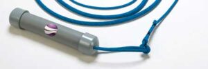
Test stations are another key component in cathodic protection system design. We typically install test stations at strategic locations to enable access for testing. Test station is a generic name. They can range from a simple lead from the pipe or buried structure, to a test station that allows for easy electrical connection. Very complex test stations may include corrosion rate probes, AC and DC coupons and remote data collection and monitoring equipment.
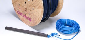
In the cathodic protection industry, buried anodes and harsh service environments are typical. To protect the integrity of the anode cabling system, the industry uses a “direct burial” cabling system. The most common in the US is a high molecular weight polyethylene cable or HMWPE. This cable insulation is generally 110 mils or more thick and is extremely robust and difficult to damage with even the harshest of handling. For some highly chlorinated environments, it is common to use a dual insulation with an inner sheath of a fluoropolymer. The common types used are PVDV (Kynar) and ECTFE (Halar). They have very similar chemical resistance characteristics.
Dual insulated direct burial cable has an inner layer of chemically resistant fluoropolymer (Kynar or Halar). This provides additional chemical resistance in highly chlorinated environments. If salts are present, these salts can result in the formation of chlorine gas which reacts with water to create hydrochloric acid. This can be very damaging to standard cabling. We highly recommend the added chemical protection of dual insulated cables in areas where high current densities occur in a chloride rich environment with minimal gas or electrolyte mobility. Deep anode ground beds, salt laden soils, and marshy areas can all create problems for standard cable. These applications call for a more chemically inert cable insulation.
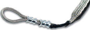
For impressed current cathodic protection systems, it is critically important that there are no nicks, cuts or cracks in the cabling or any cable connections/joints. This is especially critical for the anode cabling tied to the positive side of the power supply. If any part of the anode cabling system is compromised, and the copper conductor has an electrical path back to the environment, then the copper becomes an unintended anode. It will begin to very quickly consume, leading to an open circuit and an inoperable CP system. Thus, it is very critical on the anode side that every splice or connection is completely water tight and that all of the cable insulation is in good condition.
RMU is short for Remote Monitoring Unit. In cathodic protection remote monitoring, RMUs are commonly used to monitor, and in most cases control the performance of rectifiers in impressed current cathodic protection systems. We also apply RMUs to test stations, critical bonds and other monitoring applications. A variety of technologies are available including broadband, cellular, and satellite communications to enable system monitoring and control.
An interrupter is a sophisticated switch we can use to interrupt the operation of a rectifier. The interrupters used today automatically synchronize from a satellite signal allowing for numerous interrupters to synchronize to the same timing so that the OFF data collected is accurate. Many new pipeline rectifiers feature built in interrupters that we can energize remotely for surveys and for CP system testing.
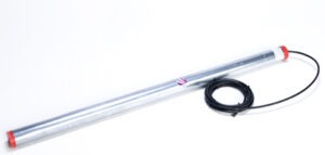
Sometimes referred to as a deep anode well or deep anode ground bed, a deep anode system is often an effective means of injecting a large amount of current into the earth from a single location with a very small surface footprint. We use conventional drilling equipment to drill a hole approximately 200-400 feet deep. Then, we lower one or more anodes into the hole before backfilling the hole. We locate the anodes sufficiently far enough from the surface to be able to consider them electrically remote from the structure. As a result we are able to project current into a congested underground environment or distribute current for miles in each direction for isolated pipelines.
The cathodic protection electrochemical reaction generates gas as part of the reaction process. This also liberates electrons to allow current to distribute through the electrolyte. In most environments that gas is able to diffuse or discharge somewhere. However, in those rare cases where the generated gas cannot migrate away from the anode surface, the gas can actually block the flow of electrons and choke the cathodic protection reaction. This is more common within deep anode systems where a hole is bored from the surface down into the earth, and the surrounding environment around the bore hole may not be very permeable thus trapping gases. Most deep anode systems use a vent pipe to allow gasses to vent away to prevent gas blockage.
Vent pipes are small diameter piping with drilled holes or cut slots that allow gases to vent away from the anode during the cathodic protection process. This reduces the buildup of gasses around the anode or the concentration of low pH hydrochloric acid that can form when excess chlorine gas is available and not vented away. This low pH environment can attack HMWPE cable insulation and result in premature failure of the cabling.
Almost all buried anodes have some form of backfill material. It is either built into the anode packaging or supplied externally for installation. Impressed current anodes generally use a coke backfill. The primary role of the coke backfill is to provide a uniform low resistance environment into which the anode can easily discharge current. This helps to reduce any issues with poor earth contact of the buried anode. In addition, it increases the anode’s effective size reducing the anode backfill to earth resistance.
Carbon itself can act as an impressed current anode. When another impressed current anode is installed in a coke backfill, some of the coke backfill will act as an extension of the impressed current anode. To the extent that carbon is consumed, the impressed current anode consumption is likely reduced. How fast the coke backfill consumes and how much of a positive impact that has on the actual anode life is very much site specific. Variables include coke column quality, coke particle compaction, moisture level, and particle shape.
There are two conduction modes for electrons. With electronic conduction, the electrons flow from the anode through the coke. As an extension of the actual anode, the electrochemical anodic reaction occurs from the carbon to the environment. As a result, the carbon is a reactant. Ionic transfer takes place where the current is generated at the anode and then flows along a moisture path on the outside of the coke particles. This does not involve the carbon as a primary reactant and thus no consumption occurs. The bottom line is this: it is difficult to know how an individual installation will operate or at what rate the backfill will consume.


