The US is constructing an increasing number of very large solar power generation farms, which brings about the question–what about corrosion? This new article explores solar farmsteel pile corrosion. Do the buried galvanized steel piles supporting solar arrays meet service life requirements?
Galvanized steel pile corrosion can occur in as little as five years.
Big Footprint
We continue to construct an increasing number of solar power generation facilities. The United States plans even more as it continues to pursue policies encouraging renewable energy development.
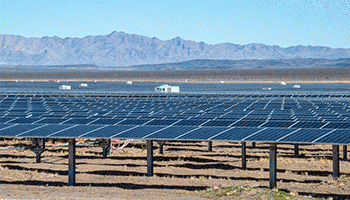
The economies of scale make these facilities more competitive with other electrical generation technologies. These utility-scale solar farms have a capacity of anywhere from 1 MW to 1000+ MW. One feature of these solar farms is their physical footprint. The average solar farm requires 6-8 acres of land to support the tens of thousands of PV cells necessary to generate electricity at this scale.
For example, the Mammoth Solar Farm project in northern Indiana, once completed, will have a generation capacity of 1650 MW. And it will cover an area of 13,000 acres and use more than 2.85 million solar panels. This is the largest project in the US and should become fully operational in 2024.
Steel Piles That support Solar Arrays: What About Corrosion?
Given these facilities’ size, cost, and anticipated service life, a fair question to ask during the design phase is: what about corrosion? Specifically, the buried support structures that hold the solar arrays in place.
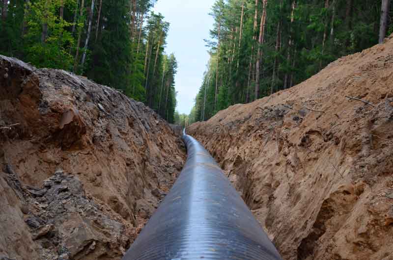
Typically, construction crews drive or screw galvanized steel piles into the soil to support the solar panels’ frames. Galvanized steel piles generally have a good service life in most environments for this application. However, as with all steel structures, they are subject to corrosion. Eventually, steel pile corrosion will adversely affect the support structure’s integrity.
Therefore, solar farm operators should consider the impact of corrosion on the service life of the galvanized piles during the project’s design phase.
Start with The Piling Details
The first step in the corrosion assessment process is to know your piles.
Any sizable solar farm project will require thousands of steel piles. The type of pile and the galvanizing thickness significantly impacting the project cost.
Unfortunately, structural engineers often do not consider corrosion when sizing the piles. They are keenly aware of loading concerns and select the pile to use based on a detailed soil load-bearing analysis and wind load analysis. They consider how big and how deep the piles need to be to support the predicted mechanical loads. This is often the only consideration. As a result, any conversation regarding corrosion is often relegated to – don’t worry, the piles are galvanized.
How Corrosive is the Environment?
But even galvanized piles are subject to corrosion, and in a highly corrosive environment, that service life might be much lower than expected. Therefore, additional corrosion mitigation measures, such as cathodic protection, might be warranted in some cases.
Given the massive footprint covering hundreds to thousands of acres these sites require, a thorough corrosion assessment for the entire area is warranted.
Typically, Geotech firms are contracted early in the project to perform detailed soil testing across these sites. This testing provides the requisite soil load capacity data to design the structural supports properly. While performing the site-wide testing, these firms will often perform some representative soil resistivity testing. While these sample soil resistivity tests may indicate the soil’s corrosiveness, they are often insufficient to evaluate correctly.
MATCOR Study: A Soil Testing Analysis
In one study performed by MATCOR, a comprehensive soil testing analysis found that much of a solar farm was in moderately corrosive soils. Still, a significant part of the facility was in very corrosive soils. In addition, the service life calculations varied significantly for the piles depending on their location within the solar farm. Estimated life ranged from 17 years to 30+ years.
Another factor in the service life calculations is the anticipated degradation of the piles during installations. The impact on the zinc coating can vary significantly depending on the soil characteristics.
Steel Pile Corrosion: How Long Will the Steel Piling Last?
The first phase of the service life of driven steel piles is the outer zinc layer of the galvanized steel pile. Zinc acts as both a coating and a galvanic anode. As the zinc layer is consumed, the underlying steel substrate is exposed. Therefore, the estimated service life, in simple terms, is the anticipated service life of the zinc coating plus the expected service life of the steel substrate.
We define the service life for solar structural galvanized steel piles as some allowable percentage thickness loss before compromising the pile’s integrity.
There are a lot of factors that affect the pile’s corrosion rate, including:
Presence of copper grounding bonded to the pile
Degradation of the zinc coating during the driving of the pile
Differential soil resistivity strata
Differential oxygen levels/aeration
Location of the water table in the area of buried piles
One of the biggest drivers of accelerated corrosion for piles is the presence of copper grounding. When steel piles are connected to a copper grounding grid, their service life can be significantly reduced as the zinc coating layer and the underlying steel substrate act as galvanic anodes. This can be very impactful in low soil resistivity environments.
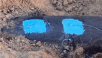
Significant Steel Pile Corrosion Can Occur in as Little as Five Years
In some extreme cases, corrosion of the galvanized piles can be structurally significant in less than five years of service. In most cases, the service life in corrosive environments can be anywhere from 10-25 years of service. A service life of more than 50 years in low-corrosivity soils might be achievable.
Solar farms are a growing part of our electrical generation portfolio and will continue to see substantial investments in the next several decades. Given the footprint and cost of these facilities, design engineers should seek corrosion assessments from qualified corrosion engineering firms such as MATCOR to confirm that the piling systems used to support the solar arrays meet the facilities’ service life requirements.
If you need assistance with galvanized steel pile corrosion protection, please contact us. We will respond by phone or email within 24 hours. For immediate assistance, please call +1-215-348-2974.
Exothermic welding and pin brazing are two methods to connect a cathodic protection system to the protected steel structure. These connections route back to the rectifier to complete the circuit for an impressed current cathodic protection system. Or they connect to the anode lead cable in a galvanic anode system. They are an essential part of any cathodic protection system.
Exothermic welding and pin brazing cathodic protection connections resulted from historical needs in the railroad industry. In addition, both have a long history of use in the cathodic protection industry.
MATCOR has the experience and capability to use either connection technology depending on the client’s specifications or requirements. In the absence of a customer preference, MATCOR generally defaults to pin brazing for CP applications.
Exothermic Welding for CP
The older of the two technologies is Exothermic or Thermite welding. More prevalent in United States specifications, this technology utilizes the heat generated from the reaction when you ignite a mixture of Aluminum powder and Iron Oxide III (ferric oxide Fe2O3). The resulting reaction is vigorously exothermic, generating temperatures more than 2000 C – sufficient to create molten iron.
Initially developed by German Chemist Hans Goldschmidt in 1893, exothermic welding connected steel rails on the Essen train line. In the 1930s, the technology gained widespread use for connecting bonding cables to railroad ties. This was thanks to the efforts of Charles Cadwell, a physicist for the Electric Railroad Improvement Corporation (ERICO.)
The Cadweld connection process has changed very little over time. It involves cleaning the structure surface down to the bare metal and laying the connector attached to the structure in a graphite mold. Next, you place an appropriately sized cartridge containing the aluminum powder and ferric oxide ready for igniting in the mold. Finally, using an ignitor sparks the reaction. As a result, an iron slug melts and flows over the copper conductor, welding it to the steel surface.
Pin Brazing for CP
Like exothermic welding, the railroad industry developed the second standard cable-to-structure technology—pin brazing.
In Sweden in the 1950s, high heat from thermite welding caused grain growth in the copper cable. As a result, connections to the rails were subject to fatigue failures from cyclical stresses associated with the movement of the rails as trains passed.
To solve this issue, the railroad industry developed lower-temperature joining technology using brazing. Brazing uses a range of silver-based filler metals to achieve the bond. These filler metals have a melting temperature between 620 and 970 C – well below the temperatures reached during exothermic welding.
Commonly specified in European standards, the pin brazing process has remained fundamentally the same since the 1950s, with some refinements to the equipment.
The pre-assembled welding pin and the pin brazing gun are the keys to pin brazing. The pin consists of a stud with a defined amount of flux encapsulated in the brazing metal. When you press the trigger, current flows through the pistol via the pin to the steel pipe. At the same time, an electromagnet is energized, drawing the pin holder and pin away from the steel surface, forming an electric arc. The arc heats the steel and starts to melt the tip of the pin. As a result, it causes the flux to melt and flow onto the steel. The electromagnet de-energizes when the current flow ceases, and the spring forces the molten stud onto the fluxed pipe surface. With the arcing stops, solidification is very rapid.
Comparing Exothermic Welding and Pin Brazing for Cathodic Protection Connections
Safety
Both methods are safe procedures when trained personnel follow the correct procedures. Neither method poses any environmental threat, although users should be sure to properly store and handle the thermite powder charges. For thermite welding, the process can be sensitive to moisture which could vaporize on contact with the molten iron slug. As a result, the potentially dangerous hot metal can be spat out of the mold. For this reason, you should conduct the pin-brazing process in damp environments and offshore applications.
Cathodic Protection Connection Reliability
Both connections have been used extensively and are widely accepted in cathodic protection. Unfortunately, no published data detailing the reliability of either connection technology exists, and reports of Cathodic Protection connection failures are infrequent and anecdotal. Lab testing on tensile load indicates that pin brazing is a slightly stronger bond; however, the loads at failure far exceeded any load possible in regular service. Nevertheless, both techniques will provide reliable, low-resistance connections when properly performed.
Metallurgical Effects
Both processes are thermal and will affect the metallurgical condition of the pipe. Many piping codes typically advise that the design consider the impact of any changes in the parent metal due to localized heating during the attachment process. Microhardness testing has shown that both connections are safe for the normal range of carbon steel pipe; however, some consideration must be given to thin-walled structures. Pin brazing results in lower temperatures and greater process control and should be considered for all thin-walled steel and alloyed piping.
Effects of Cathodic Protection Connections on Internal Coating and Fluids
Using thermal bonding to the exterior pipeline wall of a pipeline filled with highly flammable hydrocarbons requires some consideration. In addition, where internal coatings exist, it is reasonable to question whether or not thermite welding or pin brazing might damage the interior coating. Based on testing, the inner wall temperature rises more with thermite welding than with pin brazing; however, neither method’s results were sufficient to give any reason for concern.
If you need assistance with a cathodic protection assessment, please contact us. We will respond by phone or email within 24 hours. For immediate assistance, please call +1-215-348-2974.