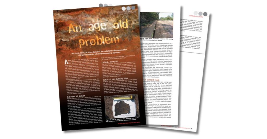
In his article for World Pipelines, Ted Huck of MATCOR tackled a pressing issue for pipeline operators: the challenge of managing aging pipeline coatings and maintaining effective cathodic protection (CP). The solutions outlined in this article—particularly the use of linear anodes—remain as relevant and impactful as ever.
Huck explores cost-effective alternatives to recoating pipelines, focusing on improving CP distribution and reducing costs. These systems, which distribute CP current evenly along the pipeline, address key issues associated with deteriorating coatings, including:
Poor current distribution and high localized potentials.
Increased operating costs and reduced efficiency of traditional CP systems.
The high expense and disruption caused by recoating.
Case Study: Saving $1.5 Million with Linear Anodes
Huck highlights a 5-kilometer pipeline segment where installing linear anodes saved over $1.5 million compared to recoating. The system not only extended the pipeline’s service life but also demonstrated superior performance, making it a valuable tool for operators worldwide.
Huck’s insights continue to guide pipeline operators in rehabilitating aging infrastructure efficiently and economically.
To get in touch with our team of cathodic protection and AC mitigation experts for more information, to ask a question or get a quote, please click below. We will respond by phone or email within 24 hours. For immediate assistance, please call +1-215-348-2974.
MATCOR’s Ted Huck presented at the Middle East Corrosion Conference on innovative strategies for pipeline rehabilitation, detailing advancements in cathodic protection technology over the decades.
Innovative cathodic protection systems address challenges like aging coatings and poor current distribution. Huck’s presentation explores:
The history and advancements of linear anode technology.
Installation methodologies, including trenching, cable plowing, and horizontal directional drilling.
Case studies demonstrating successful pipeline rehabilitation.
To discover how linear anodes provide localized cathodic protection, enhance current distribution, and extend the lifespan of pipelines without the need for costly recoating, read the full paper or view the presentation.
To get in touch with our team of cathodic protection and AC mitigation experts for more information, to ask a question or get a quote, please click below. We will respond by phone or email within 24 hours. For immediate assistance, please call +1-215-348-2974.
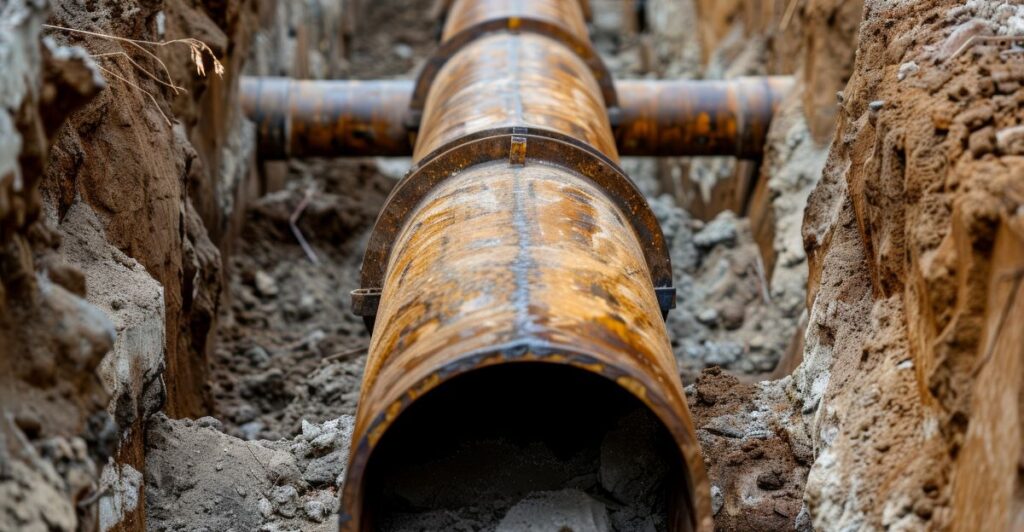
As pipeline coatings age, their ability to prevent external corrosion diminishes. MATCOR highlights cost-effective strategies to rehabilitate pipelines with aging coatings in a Materials Performance article.
From advanced cathodic protection systems (CP) to high-performance recoating solutions, the article explores practical solutions to extend pipeline service life while addressing challenges like soil stress and coating disbondment.
To get in touch with our team of cathodic protection and AC mitigation experts for more information, to ask a question or get a quote, please click below. We will respond by phone or email within 24 hours. For immediate assistance, please call +1-215-348-2974.
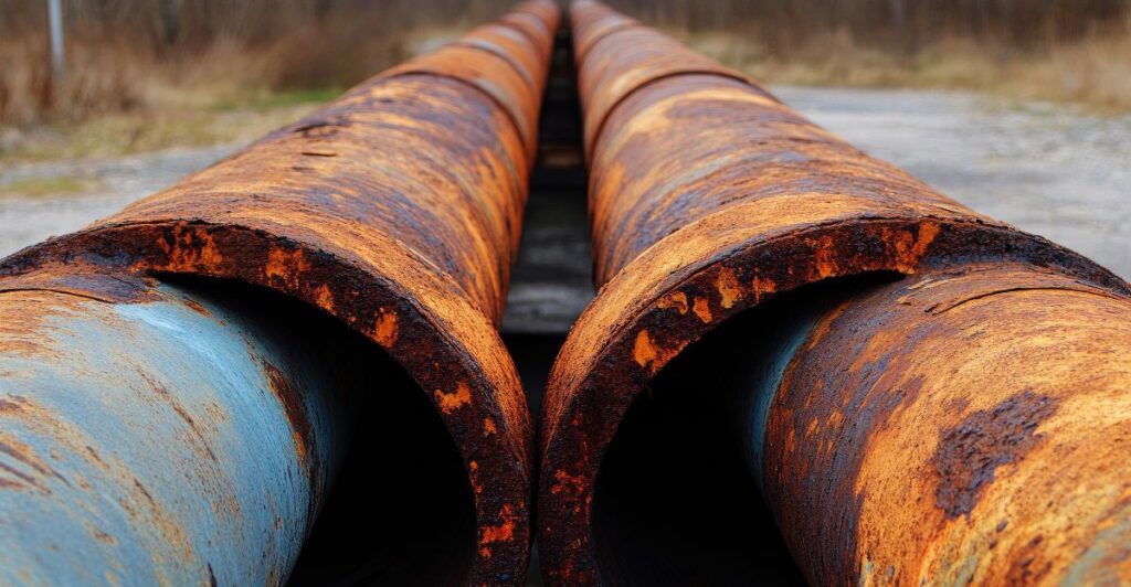
Pipelines are a crucial part of the US infrastructure, but they face a serious challenge: corrosion. This guide explains pipeline corrosion, the different types, and how to prevent it to avoid costly and dangerous failures.
The Problem of Pipeline Corrosion in the United States
The United States has over 2,225,000 kilometers of pipelines transporting oil and natural gas. No other country comes close—Russia, in second place, has approximately 260,000 km. These pipelines are owned and operated by hundreds of companies and regulated by the US Department of Transportation’s Pipeline and Hazardous Materials Safety Administration (PHMSA).
Experts consider pipelines very safe—roughly 70 times safer than trucks1 and 4.5 times safer than rail2. However, many pipelines are at least 50 years old. This increases the risk of corrosion, which threatens their safety and reliability.
Why Pipeline Corrosion Prevention is Critical
Corrosion is a natural process where metal electrochemically reacts with the environment and deteriorates over time. Without regular maintenance and monitoring, this can lead to leaks or even pipeline ruptures.
The good news? Corrosion is completely manageable. By using the right technologies and maintenance practices, pipeline operators can manage corrosion and prevent failures.
Several strategies exist to prevent corrosion, depending on whether it occurs internally or externally.
Preventing External Corrosion of Pipelines
The two most effective methods to prevent external corrosion are:
Pipeline coatings: These create a protective barrier between the pipeline and its environment. However, installation can damage them, and they can wear out over time.
Cathodic protection systems: This method uses electrical currents to prevent the metal from corroding and requires frequent testing.
These methods work well, but require regular monitoring and maintenance to remain effective.
Preventing Internal Corrosion of Pipelines
Internal corrosion occurs when contaminants in the oil or gas being transported react with the pipeline. Common contaminants include oxygen, hydrogen sulfide, carbon dioxide, chlorides, and water. The severity of this corrosion is influenced by several factors, including:
The concentration of contaminants
The combination of different contaminants within the pipeline
Operating pressure and flow velocity
Pipeline design and holdup points
Operating temperature
To effectively manage internal corrosion, operators must use a combination of assessment and prevention strategies, including:
Reducing contaminants before they enter the pipeline.
Applying internal pipeline coatings to create a protective barrier.
Injecting inhibitors to minimize corrosion reactions.
Frequent internal cleaning to remove residues.
The Role of Internal Corrosion Direct Assessment (ICDA)
Assessment is the foundation of effective corrosion management. Internal Corrosion Direct Assessment (ICDA) identifies high-risk areas and helps operators prioritize maintenance. ICDA is particularly valuable for:
Evaluating risks based on contaminants, flow conditions, and pipeline design
VCIs are an advanced solution for preventing internal corrosion. They diffuse and bond with internal surfaces to create a protective barrier against water and oxygen.
VCIs are especially effective when used alongside other strategies, such as cathodic protection.
To explore the technology and benefits of VCIs across industries, visit our Vapor Corrosion Inhibitors guide.
While pipeline corrosion is a serious issue, it can be effectively managed through proper monitoring and preventative measures. Whether facing internal or external corrosion, a strong integrity management program is essential to lowering the risk of failure.
To get in touch with our team of cathodic protection and AC mitigation experts for more information, to ask a question or get a quote, please click below. We will respond by phone or email within 24 hours. For immediate assistance, please call +1-215-348-2974.
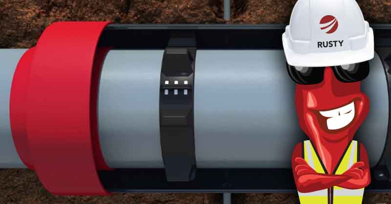
Rusty chats with Ted Huck, Director of Manufacturing and Quality Assurance.
Rusty: Ted, thanks for taking a few minutes to discuss the application of VCI for cased pipeline crossings. First, what is a cased crossing?
Ted: Cased pipeline crossings are a common feature in the industry. They are used primarily at road and rail crossings.
The casing (also referred to as the encasement pipe) is a larger diameter pipe that is designed to take the loading from vehicle or train traffic on the road and absorb/deflect that loading from the carrier pipeline inside the casing.
In addition to the encasement pipe and the carrier pipe there are other key elements to a case crossing. Notably, there are non-metallic spacers that position the carrier pipe inside the encasement pipe, and dielectric end seals that prevent the ingress of water and soil. Finally, there are vent pipes on each end of the casing. These provide a warning and route product to a safe location in the event of a pipeline leak inside the sealed casing.
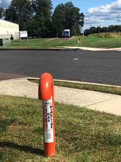
Pipeline Casing Vents on each side of a road crossing in Chalfont, PA
There are tens of thousands of these cased pipeline crossings throughout the United States.
Rusty: So, what are the corrosion challenges with cased crossings? What can go wrong?
Ted: Pipeline operators have found that an inordinate amount of pipeline leaks occur at cased crossings. Therefore, operators are actively looking to eliminate these whenever possible.
It is important to evaluate existing casings periodically. Two mechanisms can adversely affect pipeline integrity at cased crossing locations.
The first is a metallic short. This results from the carrier pipe shifting inside the encasement pipe. It causes a direct metallic contact between the carrier pipe and the encasement pipe.
Shorted casings can significantly impact the cathodic protection system protecting the pipeline. This is due to the encasement pipe drawing CP current away from the carrier pipe. Shorted casings also increase the risk of AC Interference, AC induced corrosion and shock hazards at the above ground vents.
The second casing failure mechanism is related to the integrity of the end seals over time. In many cases, these end seals develop leaks allowing water and soil into the space between the carrier pipe and the encasement pipe. This creates an electrolytic couple. The introduction of these contaminants can lead to accelerated rates of corrosion of the carrier pipe.
Rusty: What are my options if my casing is shorted or the carrier pipe exhibits signs of corrosion?
Ted: You can employ several strategies to address corrosion concerns with cased pipeline crossings:
Excavate ($$$). With this first approach, you dig up the casing and either remove it entirely or repair it. Repairing involves exposing one or both ends to repair the end seals and if necessary, readjust the spacers to clear the shorted condition. This is a construction intensive operation but, in many cases, can restore the cased crossing to an as-new condition.
Fill with Wax ($$). A second approach is to fill the annular space with a high di-electric wax. There are a variety of wax treatment options available. Typically, the wax is introduced through the vents and every effort is made to fill the entire annular space with the wax material.
The wax acts much like a coating covering the carrier pipe and prevents corrosion like a coating system. The industry has found that this is not always a complete solution, since voids in the wax fill can allow pockets of corrosion.
Fill with VCI ($). The third approach is to pump the annular space full of an aqueous gel or powder, or a slurry formulation of corrosion inhibitor material. The corrosion inhibitor is typically a combination of volatile corrosion inhibitor (VCI) and soluble corrosion inhibitor (SCI) that combine to stop corrosion. This method has received industry and regulatory approvals over the past decade and is gaining market share as operators become familiar with the technology and its advantages.
Rusty: How challenging is it to fill a pipeline casing with wax or with VCI?
Ted: Both operations are similar in many respects.
For both wax and VCI filling installations, repairing the existing casing is often the first step. You inspect the end seals and spacers, and where appropriate, remove and replace them.
The interior space between the carrier piping and the casing is flushed clean of dirt and other debris. Once the repairs are complete and the ends are sealed, you calculate the volume of product needed to completely fill the space between the carrier pipe and the casing.
Then the product is prepared according to the manufacturer’s recommendations. Pumping or filling the space is different for each of the type of fill, but both technologies require appropriate equipment and experienced installers.
Wax fills typically use a heated wax product for larger casings. Cold flowing wax can be used on some smaller casings.
For wax fill applications, the space between the carrier pipe and the casings must be completely flushed and cleared out during the repairing of the end seals.
Even with a well-prepared casing, achieving a complete wax fill is very difficult. Voids and gaps are typical.
One published study of 143 wax filled casings found that the average fill was 81%.
For VCI installation plans, the appropriate vapor corrosion inhibitor types and delivery methods are an important considerations. The VCI slurry needs to be mixed properly before being pumped into the casing using the appropriate pumping equipment.
Because VCI applications typically use an aqueous slurry with an experienced installer, VCI is easier to install than a similar wax application. The VCI component is designed to release from the aqueous solution after being pumped into the casing to fill all vapor spaces. Therefore, concerns over gaps and voids are non-existent.
Rusty: What about concerns with bacteria in the space between the carrier pipe and the casing?
Ted: This is an area where the two fill types differ significantly.
For wax filled casings the goal is to completely fill the space with wax displacing or encapsulating any bacteria. However as noted above, areas of incomplete fill or voids in the wax encapsulation can leave space for bacteria to continue to grow.
With VCI, the VCI chemistry increases the pH (9 to 9.5 is typical) inside the casing. This range makes it very difficult for bacteria to grow, while also neutralizing any acid secretions from the bacteria.
Rusty: Can Cathodic Protection help with protecting carrier pipes inside filled casings?
Ted: With wax filled casings, the wax has a high dielectric value and does not allow cathodic protection current to pass.
This prevents the carrier pipe and casing from draining cathodic protection current from the pipeline CP system, but it also provides no protection to the carrier pipe. The VCI gel that sets up is conductive and allows cathodic protection current flow. Some evidence supports the benefit of cathodic protection and VCI working in tandem to prevent corrosion.
Rusty: How can pipeline operators monitor the effectiveness of any cased crossing corrosion solution?
Ted: Most pipelines can be assessed using In Line Inspection (ILI). These pipelines can use smart tools with MFL, and other tools, to assess and monitor corrosion in the carrier pipe with a casing.
For wax filled casings, if ILI is not an option, there are no other good monitoring options. For pipelines that cannot be inspected using smart pig technology, conventional above ground pipeline testing technology is limited.
For VCI filled casings, we employ various technologies in conjunction with VCI including coupons, ER Probes and /or UT probes installed between the carrier pipe and the pipeline casing, to monitor the effectiveness of the VCI in the casing. These are installed and connected to RMUs for remote monitoring, or wired to a local junction box for direct reads during surveys.
Rusty: Any final comments on Cased Pipeline Crossings?
Ted: Cased crossings are a challenge for pipeline owners.
Should you have any additional questions, please reach out to a MATCOR account representative for more information. As a full-service corrosion company, we have extensive experience and a wide range of capabilities including both wax and VCI installations for casings.
Have questions or need a quote for corrosion prevention materials or services? Contact us at the link below. For immediate assistance, please call +1-215-348-2974.
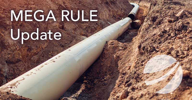
Recently PHMSA issued its final rule expanding Federal pipeline safety oversight to all onshore gas gathering pipelines. Known as the PHMSA Mega Rule, this ruling has tremendous impact on the US pipeline industry, adding significant scope to the current pipeline integrity management requirements.
The final rule affects tens of thousands of miles of previously unregulated gas gathering pipelines. Also, pipeline operators have to report safety information for more than 450,000 miles of gas gathering lines governed by Federal reporting requirements.
Some of the impacts of the PHMSA MEGA rule on the industry include:
An approximately 20% increase in the number of regulated pipelines in the United States The addition of 20% more regulated pipelines had a significant impact on an industry where highly qualified integrity professionals and related services were limited in supply and the industry was already struggling to meet demand. These additional pipelines required significant integrity resources.
Expedited reporting requirements The time restrictions for implementing the new rule were accelerated, with initial reporting requirements having started in July 2020. The time to comply with these regulations was reduced by 20% from the initial draft order timeline.
Increased cathodic protection requirements Many pipelines that previously were not regulated and have not had proper CP required a properly designed, maintained, and tested cathodic protection system.
What Does The Final Rule State?
The final rule expands PHMSA’s Part 192 to gas gathering lines that fall within Class C, a new pipe category. Within Class C, the requirements for operators vary based on a risk scale. The risk scale varies with pipeline diameter and proximity to people (BIHO – buildings intended for human occupancy).
For pipelines that meet these criteria, the requirements for corrosion control (CFR 49 Part 192 Subpart I – Requirements for Corrosion Control) will now apply to these previously unregulated lines. The Part 191 incident and annual reporting requirements have expanded to include all previously uncontrolled gas gathering lines, regardless of Class.
How Can MATCOR Help Company Operators Comply with PHMSA Mega Rule?
Gas producers and midstream gas pipeline operators have to reevaluate their pipeline networks to incorporate any previously uncontrolled pipelines to comply with CFR 191 and CF 192. MATCOR offers a wide range of cathodic protection and integrity services to help our customers including:
If you are looking for help complying with the PHMSA’s new Mega Rule and its additional requirements, please contact us. We will respond by phone or email within 24 hours. For immediate assistance, please call +1-215-348-2974.
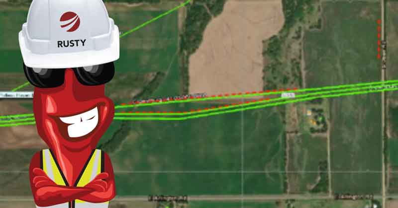
Rusty and Josh Johnston chat about a recent project and case study involving the use of linear anodes for hard to reach places.
This month, MATCOR exhibited at the AMPP Central Area Conference held in Kansas City. MATCOR’s Mr. Josh Johnston, along with Mr. Chad Farris of Energy Transfer, jointly presented a paper—a case story using linear anodes as a shallow horizontal anode bed installed along two pipelines in central Kansas.
Rusty: Josh, tell us how it felt to finally be in a real-life conference interacting with people in person after the last year and half of cancelled conferences and virtual conferences.
Josh: It is always great to get to interact with our friends and industry colleagues, clients, suppliers and competitors to share information and discuss the challenges that our industry faces—especially given the events of the past couple of years. Presenting this paper was a great opportunity to highlight the use of linear anodes to protect hard to reach areas on older pipelines.
Rusty: Can you describe the problem that you covered in your presentation?
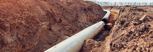
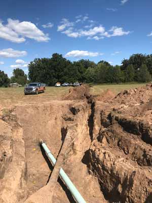
Josh: Energy Transfer had two older pipelines that were not meeting criteria in a rural location. As is typical in a lot of pipeline cathodic protection applications, the pipelines were being protected by impressed current anodes located at road crossings where power was readily available. The roads ran parallel to each other and were located one mile apart. The pipeline traversed these two roads and the area in between was mostly farmland. As a result of the age and coating condition, the shallow horizontal anode beds, located at the road crossings, were not able to project much more than a ¼ mile from each end, leaving approximately ½ mile in the center under protected. This was clearly identifiable in the close interval survey (CIS) data.
Rusty: Couldn’t they simply increase the current output of the existing shallow ground beds at each end of the pipeline to drive more current to the center section in between?
Josh: They tried that approach, and it did not work, raising concerns that driving excessive current onto these older pipelines could actually make the situation worse by further disbanding any coating close to the existing ground beds.
Rusty: So where did MATCOR come into this project
Josh: MATCOR proposed linear anodes be installed parallel to each of the pipelines in the area between the two roads. MATCOR developed the very first MMO (mixed metal oxide) linear anodes over 30 years ago and we have the most experience designing linear anode CP systems.
Rusty: So it sounds easy, you take a couple of ½ mile segments of linear anode, trench them in parallel to pipeline and run a couple of long extension cord cables back to the road where there is power.
Josh: Well it does sound easy; however, in practice it is critical that any linear anode design carefully addresses voltage drop, and that the power feed cabling is configured so that each anode segment output is balanced. If this is not engineered properly, you could have a large disparity in the voltage being applied on one end of the anode segment relative to the other end. This would result in a very uneven distribution of current. Discussing the design considerations for the power feed cabling was the primary focus of this presentation.
Rusty: So how did it work out?
Josh: MATCOR was able to use some creative cabling analysis and routing to assure that the voltage difference from one end of an anode segment to the other was no more than a 10% variance. The post installation and commissioning CIS data delivered an outstanding current distribution.
Rusty: Thanks for providing a very quick overview of your presentation—any final thoughts or comments?
Josh: When designed properly, linear anodes can be a real problem-solving solution for older pipelines with current distribution and attenuation issues.
Have questions or need a quote for linear anodes or installations services? Contact us at the link below. For immediate assistance, please call +1-215-348-2974.
Internal pipeline corrosion is a significant challenge for maintaining pipeline integrity, particularly during construction or after hydrotesting. Vapor Corrosion Inhibitors (VCIs) provide a targeted solution for protecting internal pipeline surfaces and mitigating corrosion risks.
Internal corrosion occurs when contaminants such as water, oxygen, and bacteria interact with the metal surfaces inside a pipeline. This risk is especially high after hydrotesting, a mandatory step for verifying pipeline integrity.
During hydrotesting:
Residual moisture and bacteria often remain even after draining and drying, creating a highly corrosive environment.
Hydrotesting introduces water into the piping to ensure there are no faulty welds and that the piping system can handle design pressure without leaks. Unfortunately, this testing can also introduce bacteria, which exacerbate corrosion risks.
Even with efforts to dry internal surfaces, residual moisture and contaminants can accelerate metal degradation, compromising long-term reliability.
How VCIs Work for Pipelines
VCIs are chemical compounds designed to protect pipelines by:
Diffusing and adsorbing onto metal surfaces to create a molecular-level protective barrier.
Blocking water and oxygen from reacting with the internal metal surface.
Providing long-lasting protection for months or years, depending on application conditions.
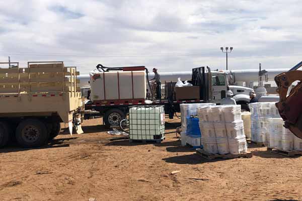
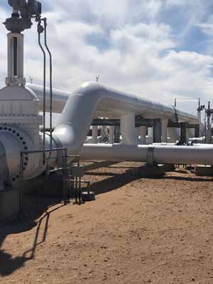
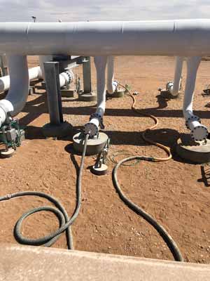
For pipeline preservation applications, VCI chemicals are typically mixed with water into a slurry. This slurry is then pumped into the piping manifolds using a series of injection pumps and injection ports, delivered via hoses from multiple mixing tanks.
VCIs are particularly effective for hard-to-reach areas within pipelines, such as manifolds and intricate piping systems, where traditional methods may fall short.
VCI Case Study: West Texas Pipeline Reservation Project
MATCOR completed a significant preservation project at a newly constructed pipeline station in West Texas. Highlights of the project include:
Injecting over 24,000 gallons of VCI solution into multiple above-ground manifolds after hydrotesting.
Adding methanol (anti-freeze) to the slurry mixture to ensure freeze protection during winter.
Successfully mitigating corrosion risks while the remainder of the construction continued.
This project demonstrated the effectiveness of VCIs in preserving pipeline integrity under challenging environmental conditions.
Enhancing VCI Effectiveness with Complementary Measures
VCIs are a powerful tool for internal corrosion prevention, but their effectiveness is maximized when used in conjunction with other measures:
Reducing contaminants before pipeline entry: Ensures that corrosive agents are minimized, allowing VCIs to focus on existing risks.
Internal pipeline cleaning: Removes residue and deposits that can interfere with VCI diffusion or create localized corrosion.
Cathodic protection systems: Provide additional protection for pipeline areas not effectively reached by VCIs, such as crevices or air gaps.
By integrating VCIs with these measures, operators can create a comprehensive internal corrosion prevention strategy.
To get in touch with our team of cathodic protection experts for more information, to ask a question or get a quote, please click below. We will respond by phone or email within 24 hours. For immediate assistance, please call +1-215-348-2974.
Working with fellow BrandSafway company Industrial Specialists LLC, MATCOR successfully completed a turnkey pipeline recoating and cathodic protection upgrade project ahead of schedule and to the operator’s complete satisfaction.
MATCOR & Industrial Specialists team up on a complex pipeline recoating project.
Earlier this year, MATCOR purchased two state of the art dual air/hydro vacuum excavators. We have put these units to work as we expand our capabilities to include pipeline recoating services.
“We recently completed a major project in Oklahoma for a midstream client that leveraged our ‘Big Air’ vacuum excavators. This complex project challenged our existing capabilities and allowed us to draw on the resources and capabilities of our parent company, BrandSafway, to provide a full service cathodic protection upgrade and pipeline recoating in multiple locations.”—Josh Johnston, MATCOR Director of Sales
Pipeline Recoating Added to Anode Bed and Test Station Installation
The project consisted of six (6) anode bed installations and seven (7) test station installations – standard CP work for MATCOR; however, at each of the test station locations, we were also tasked with coating removal and recoating of the approximately 20 ft of pipeline exposed at each location.
The coating removal was complicated by the presence of asbestos. Prior to 1980, asbestos was typically used in a felt wrapping around the pipe along with an asphaltic (tar) outer wrap.
Asbestos can still be found in the coating of hundreds of thousands of feet of buried pipeline installed prior to 1980. MATCOR’s crew received one week of asbestos removal training to be properly qualified to identify, remove and dispose of the coating containing asbestos.
MATCOR’s parent company, BrandSafway, has in its portfolio of businesses Industrial Specialists, LLC (IS), which is an extremely well-qualified industrial coatings services team with over 35 NACE trained and certified inspectors and over 1,700 painters and supervisors.
MATCOR was able to partner with the IS Tulsa, OK office to deliver the entire project using in-house BrandSafway resources, making us a one stop shop for this level of work. MATCOR’s CP construction crews performed the vacuum excavation and asbestos coating removal, and then the BrandSafway industrial services crew performed the blasting, inspection and recoating work. One big company with a wide range of industrial capabilities.
Project Completed Ahead of Schedule
The project was executed successfully, completed two weeks ahead of schedule and to the pipeline operator’s complete satisfaction. We even identified two areas where the pipeline was directly on top of rock and the owner asked that MATCOR install a layer of rock shield over the completed recoat areas. At the end of the project, the pipeline operator affirmed that they would be using MATCOR again for similar project work.
Have questions or need a quote for cathodic protection or pipeline recoating services? Contact us at the link below.
This article provides a brief overview of the important role of cathodic protection remote monitoring systems in today’s pipeline operations. We will cover the CP equipment and features that can be monitored and how data is transmitted.
Advanced cathodic protection remote monitoring systems are critical for today’s pipeline operator.
Modern pipeline operations face increasing pressures to incorporate advanced technologies to:
Drive down operating costs
Improve system reliability
Comply with regulatory requirements
Monitor the health of their pipeline networks
Monitor the critical systems that are integral to pipeline integrity
The use of advanced cathodic protection (CP) remote monitoring systems has become a critical component in the pipeline operator’s toolbox to meet these challenges.
CP remote monitoring (and control) has proven to be a reliable and cost-effective means to oversee the proper functioning of cathodic protection systems and AC Mitigation systems that are critical to assuring pipeline integrity and the proper protection against pipeline corrosion. Where operators in the past would have to send technicians out to remote pipeline locations to collect snapshot data on a frequent basis, the smart deployment of CP remote monitoring systems can provide continuous real time data that can be accessed from any cloud connected handheld or desktop device. Additionally, a remote monitoring unit for cathodic protection is well-insulated; this construction affords them excellent protection against lightning strikes. The financial, environmental and safety impact of eliminating hundreds of thousands of windshield hours is staggering across the vast pipeline industry.
Cathodic Protection Remote Monitoring – What can you monitor?
Cathodic Protection Rectifiers – the installation of RMUs with built in interruption capabilities should be standard on all new pipeline installations and retrofitting older units can provide significant cost savings and improve CP system reliability.
DC Cathodic Protection Test Stations – with today’s continuing advances in remote monitoring technology and costs, it is quickly becoming very cost effective to install remote monitoring units on all test stations. When combined with the ability to easily interrupt all of the influencing current sources on a pipeline, regularly scheduled testing of the CP system can be performed quickly and at virtually no cost.
AC and DC Coupon Test Stations – the latest NACE guidelines for AC Mitigation (SP21424-2018*) emphasize that the localized DC current density has a significant impact on AC corrosion and gathering data on both AC and DC current densities at areas of interest/risk is critical to a successful AC Mitigation strategy. Effectively doing so requires the ability to monitor these values over time as AC loads vary during the day and seasonally.
Critical Bonds – monitoring the effectiveness of critical bonds is necessary (and in many cases required by local regulatory bodies) to assure pipeline integrity.
NACE SP21424-2018 “Alternating Current Corrosion on Cathodically Protected Pipelines: Risk Assessment, Mitigation, and Monitoring”
How does a CP remote monitoring system transmit data?
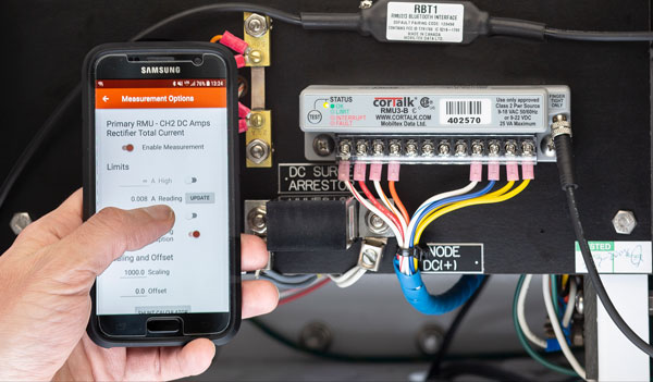
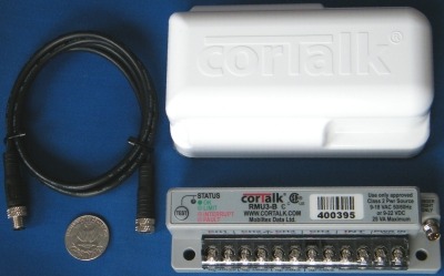
Mobiltex Cathodic Protection Remote Monitoring Unit (CP RMU)
Today’s operators have a range of options to assure that remote monitoring systems can regularly communicate data to their host data collection systems. The availability of conventional cellular networks combined with various commercial satellite systems assures pipeline operators of the ability to communicate with devices in even the remotest of locations. Your monitoring system provider can work with you to select the appropriate communications technology for each CP remote monitoring unit (CP RMU) location.
In addition to choosing how the communication is to occur, another key factor to consider is whether the communications are to be one way (monitoring only) or two-way (monitoring and control). For test station applications where data collection is the goal, one way transmission of the monitoring unit’s data is all that is required. For rectifier units, the ability to control the system output and/or the ability to initiate an interruption cycle for close interval surveys or test station polling purposes necessitates the ability of the cathodic protection remote monitoring unit to receive and act on communications as well as to transmit data.
Software Interfaces – Installing the appropriate CP RMU hardware is just one step in implementing a successful remote monitoring (and control) program. The data must be collected, stored, and accessible for the operator. Sophisticated cloud-based interfaces have been developed that incorporate critical features including firewall-friendly, password protected internet browser access. These systems allow for multiple client user accounts with configurable permission levels and automated alarm and status information including email and text alerts for designated alarm conditions.
In summary, the use of remote monitoring technology is a key component to the successful operation of any modern pipeline integrity management program. While MATCOR has extensive experience with all of the major RMU manufacturers, we have recently teamed up with Mobiltex, a leader in the field of remote monitoring, to bring state of the art technology to the pipeline and cathodic protection industry. Mobiltex’s CorTalk® line of CP RMU units combined with their CorView interface offers all the features necessary to implement a comprehensive, cost-effective, and highly robust cathodic protection remote monitoring program.
Please contact us at the link below if you have questions about cathodic protection remote monitoring, or if you need a quote for services or materials.