On the surface, applying cathodic protection to a storage tank appears straightforward. However, accurate tank cathodic protection testing is rarely that simple. The reality of validating tank bottom corrosion control is actually far more complex.
Our engineering team recently reviewed the unique obstacles facility managers face when inspecting above ground storage tanks (ASTs). Below, we outline the critical challenges in obtaining accurate compliance data and the key points from that discussion.
Why are above ground storage tank cathodic protection systems difficult to test?
From a macro level, we have a large round structure that sits on an engineered foundation – sounds simple. But the reality is that there are structure issues and electrolyte issues. Add testing challenges to the mix and tank bottom CP system testing is much more difficult than you might initially think.
What issues affect tank CP system performance and testing?
Tank Inventory Level
The inventory level in the tank is one critical issue with tank bottoms. The weight of the tank’s product pushes down on the tank bottom to ensure a more complete contact of that tank bottom with the sand cushion below the tank. The bottom of an empty tank, on the other hand, may flex. As a result, it has less intimate contact with the sand cushion.
Because of this, the potential measurements taken on a full tank are typically less negative than the same readings on that tank when it is empty. We avoid taking readings on out of service tanks. But even for tanks in service, recording the tank level when taking potential readings is a good practice.
When a tank is empty, we see a much higher resistance. The current output is much lower at the same applied voltage, so it is hard to say whether we actually have a higher current density in the areas that remain in contact with the sand.
Tank Isolation Status
Another issue with the structure has to do with isolation. When testing tank bottoms, it is important to check the tank isolation status relative to piping and earthing systems. In many cases, the tank has isolation measures in place to ensure that cathodic protection current is directed at the tank bottom, and is not being picked up from other nearby structures. When testing isolated tanks, it is important to confirm this as part of the testing process.
What are the electrolyte issues that can affect CP system performance and testing?
Tank Sand Bed
Both AMPP (formerly NACE) and API specifications recommend a high quality, high resistance sand cushion for new construction tanks and tank retrofits. The sheer volume of sand material required for just 12” of tank bed can be significant. For a 150 ft diameter tank this can be on the order of 900 tons of material. It will depend on the sand density. This can be upwards of 60 truckloads using large 30,000 lb capacity dump trucks.
Even if the sand comes from the same source, it is not a given that the sand will be entirely uniform and have the same moisture content. In extreme cases, we have seen completely dissimilar sand used in different areas of the same tank.
Once the tank is erected, it is simply not possible to confirm that the tank has a uniform electrolyte.
Moisture Content
Over time, the sand can experience swings in moisture content. And, it is not uncommon to see rainwater and flood water entering the sand foundation. This depends on the quality of the seal chime, and the nature of the tank’s secondary containment system (release prevention barrier and dikes).
Moisture content has a tremendous impact on sand resistivity and can impact cathodic protection performance. The electrolyte may change significantly over time. As a result, any native or depolarized potential readings taken during startup and commissioning cannot be used to assess polarization in subsequent years.
Additional Tank Cathodic Protection Testing Considerations
Access Under the Tank
Taking accurate and repeatable potential measurements over time is critical. Historically, the common practice has been to install fixed reference electrodes under the tank during construction.
Copper-copper sulfate reference electrodes are the most commonly used under tanks. The big problem with this type of reference electrodes is reliability over time. It is not uncommon to see inaccurate potential data within 10-15 years of service.
Tanks typically have a much longer service life than the reference electrodes installed to monitor the CP system performance. On older tanks, there is frequently a mix of “good” reference cells confirming proper CP system operation, along with “bad” reference cells that provide inaccurate readings. As a result, it is difficult to confirm that the tank is meeting criteria.
We have measured stationary electrodes that exhibit erroneous readings after just a few years. In addition, operators consider stationary electrodes inaccurate after one year. This is due to the dry conditions around the cell, not because of the efficacy of the electrode itself.
A Reference Electrode Solution
One solution is to pair the copper-copper sulfate reference electrode with a zinc type reference electrode. Zinc reference electrodes are more stable over time. They can provide effective service for the life of the tank. However, their base potential can vary from one zinc reference electrode to another. Because of this, it is often advisable to bury the zinc reference electrode along side a copper-copper sulfate reference electrode. This way the zinc reference electrode can be “calibrated” against the copper-copper sulfate reference cell.
A Newer Alternative to Fixed Reference Electrodes
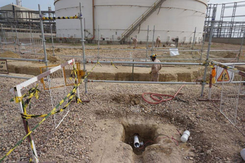
We see a growing trend towards the use of micro-slotted PVC pipe as a pull tube. This enables a calibrated reference electrode to be dragged inside the tube to take continuous “profile” readings from one edge of the tank to another. In some cases, this could be a single pull tube, while in other cases two pull tubes are installed to allow taking even more potential measurements.
When taking potential measurements using a pull tube, it is critical to ensure that the electrode in the tube has electrolytic contact to the sand around the tube. In other words, there must be enough water in the tube to facilitate this contact. Additionally, you should use a voltmeter with an input impedance greater than the standard Fluke meter 10 M-ohm resistance . There are several meters available with input impedance of 100 M-ohm and greater.
What is the appropriate criteria requirement be for tank bottom cathodic protection?
The two most applicable criteria would be -850mV Instant-Off potential and the -100mV polarization criteria and when properly applied both are applicable.
-850 mV Off Potential
This criterion can be a challenge to achieve on a large bare structure in a well-aerated environment. Therefore, many times we look to the other applicable criteria which is the 100 mV of polarization criterion.
-100mV Polarization Criteria
Two approaches can be taken using the 100 mV criteria. The first is a formation criterion which is based on comparing the polarized potential to a known baseline, or native, potential. As noted earlier, over time that baseline may no longer be valid for the tank.
The second approach is polarization decay, where the polarized potential is compared to a depolarized potential. The depolarized potential is obtained by removing the current sources and allowing the tank to depolarize for a few days to a few weeks. Again, the depolarized potential may change over time due to changes in the electrolyte. Therefore, collecting a new depolarized potential is recommended during each annual structure-to-electrolyte potential survey.
Heated Tanks
It is important to note that the 100 mV shift criterion is not valid for heated tanks that operate at temperatures above 30ºC (86ºF). Studies have found that heated structures require up to 300 mV polarization. Studies also show that areas with sulfate reducing bacteria (SRB) require similar higher levels of polarization.
Mixed Metal Systems
The 100 mV polarization criterion is also not valid for mixed metal systems. The presence of certain mill scales on steel tank bottoms can create a mixed-metal system. As a result, the validity of the 100 mV criterion may be negated. There is ongoing research into the issue of mill scale.
Finally, as noted above, a multimeter with a higher input impedance should be used when measuring potentials under tanks. For pull tube readings, there is a significant resistance through the tube. For stationary electrodes, there can be significant resistance to the surrounding dry sand, which adds a level of error. A higher input impedance meter helps to reduce this error, but it will not eliminate it.
Tank Cathodic Protection Testing Summary
Tanks can be difficult to test and without the proper training, understanding, and equipment it is all too easy to get an inaccurate picture of the actual performance of the CP system. If your tank CP system does not appear to be working, perhaps a qualified second opinion is warranted before considering more drastic measures.


 MATCOR provided the plant with a detailed proposal to design and install a complete cathodic protection system using MATCOR’s Replaceable Tank Anode system. The RTA system is based on installing MATCOR SPL
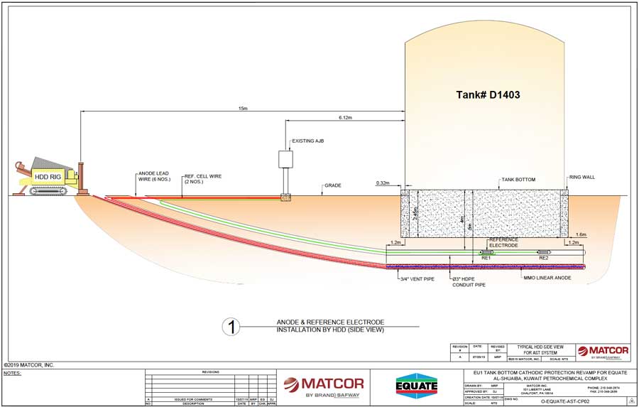
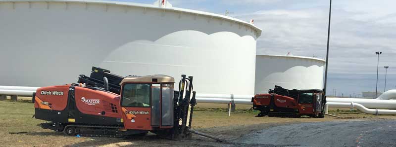
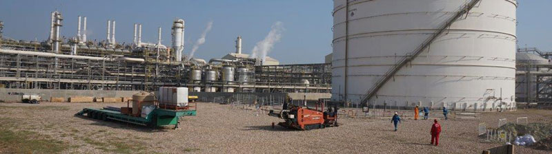
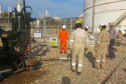 While the plant conceptually agreed with MATCOR’s solution from a technical perspective, there remained a significant concern within the plant’s operation and safety groups about drilling under this critical service tank and the possibility of a catastrophic event should the drill head drift up to the tank bottom. MATCOR put together a thorough installation procedure including detailed information on the sophisticated drill head tracking systems being utilized to assure that the drill head location was being continuously monitored throughout the bore. Utilizing an experienced local HDD drilling sub-contractor, MATCOR deputed its senior HDD installation drilling supervisor to Kuwait for the installation. Our Senior HDD Drilling Supervisor has completed hundreds of tank HDD installations in the United States and his on-site presence, along with the advanced electronic tracking package being used, assured that each bore went as planned.