What is the impact of AC interference on pipelines?
This 16-minute AC interference video training course reviews the 3 basic effects of AC interference on pipelines, including:
-
- 15-volt safety threshold
- Fault conditions
- AC induced corrosion
The summary below includes video timeline indicators so you can easily find your topic of interest in the video.
What is AC Interference?
(0:25*) AC interference is an interaction that occurs between high voltage power lines and pipelines in a common utility corridor.
*References the time in the AC Interference Video where this topic is reviewed.
1. Fault Condition Interaction Modes
In the video, our AC mitigation expert Ted Huck explains fault currents and two modes of interaction with pipelines, conductive coupling and stress voltage.
Conductive Coupling
(1:09) Conductive Coupling is a relatively rare occurrence when there is a fault condition along the power transmission line and a large amount of electricity is dumped to the earth. The collocated pipeline is subject to this discharge of electricity through arcing, defined as the flow of current through the soil. Although rare, conductive coupling can burn a hole through the pipeline and cause a catastrophic failure.
Determining the Safe Distance from Tower to Pipeline for Arcing
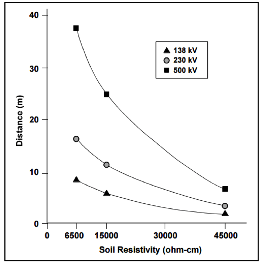
Arc Length
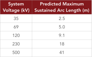
(2:16) In this segment, our AC mitigation expert describes a real customer case scenario where arcing caused catastrophic failure of a gas pipeline.
(4:01) Another issue that can occur with conductive coupling is a voltage rise radiating out from the location where the electricity is dumped to the earth. Newer pipeline coatings cannot handle excessive voltage stress.
Stress Voltage
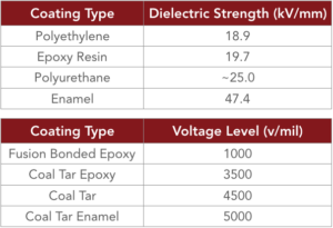
Electromagnetic Induction
(5:44) Electromagnetic Induction is a steady state occurrence where current flowing through the line creates an induced current flowing in the opposite direction along the parallel pipeline. If the pipeline is close enough to the power transmission line, and runs parallel to it for some length, it will be in the electromagnetic field that exists around the AC transmission system. Being in that electromagnetic field, it will inductively pick up current throughout the longitudinal electrical field.
Longitudinal Electrical Field (LEF)
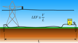
2. AC Induced Corrosion
(7:26) AC induced corrosion occurs when alternating current is picked up by the pipeline that cannot effectively dissipate back to the earth. Well coated pipelines have very few places for the current to exit the pipeline and are at risk for significant, rapid AC corrosion. Older coating systems have many defects, or natural grounding points enabling AC on the pipeline to naturally dissipate, so AC corrosion is a relatively new concern. With newer coatings, AC current continues to build until it finds a small coating holiday (typically 1-3 cm2) to exit the pipeline, risking catastrophic failure.
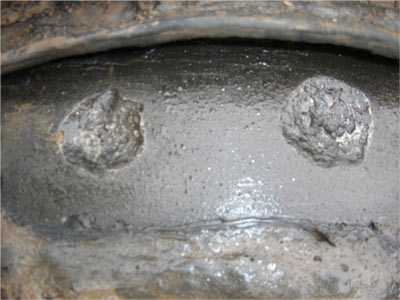
How likely is AC corrosion to occur?

Current Density Formula
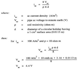
In our example, 4.4 volts AC is all it takes to cause AC corrosion. With older pipeline coatings that threshold is in the 15 volts AC range.
100 A/m² Threshold – When will AC corrosion occur?
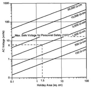
Refer to NACE Report 35110, AC Corrosion State-of-the-Art: Corrosion Rate, Mechanism, and Mitigation Requirements for additional information about the 100 A/m2 threshold.
In Europe, refer to standard BS EN 15280:2013, evaluation of AC corrosion likelihood of buried pipelines applicable to cathodically protected pipelines.
The Relationship Between AC Induced Corrosion and Cathodic Protection
(12:00)
- No cathodic protection – high likelihood of AC corrosion
- Excessive CP current, or over polarization may increase AC corrosion
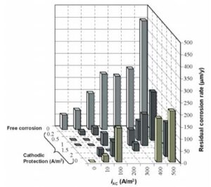
3. Safety
(12:50) Pipelines have above ground appurtenances such as valve stems and test stations that are subject to the AC currents picked up by the pipeline. These can pose a serious safety risk to workers, including shock or death. These risks are referred to as step and touch potential.
Touch Potential is defined as current flowing from touching an electrified device, through the body and down to the earth.
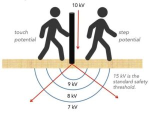
Step Potential can occur even without the worker touching the electrified device. In this case, current can flow up one foot, through the body and back down to the earth through the other foot, potentially causing serious injury or worse.
Refer to NACE SP0177-2014 (formerly RP0177), Mitigation of Alternating Current and Lightning Effects on Metallic Structures and Corrosion Control Systems, Paragraph 5.2.1.1 for additional information on the 15 volt safety criteria.
Summary
This AC interference video reviews the 3 basic effects of AC interference on pipelines, including the maximum 15 volt safety threshold—how much voltage can accumulate on the pipeline before it becomes a safety hazard to a person touching the pipeline? If there is more than 15 volts AC, we must do something to drop that voltage. Then there are rare but potentially catastrophic fault conditions, or the dumping of current to the earth. Finally there is AC induced corrosion, a result of the interaction of the electromagnetic field generated by current flowing through the lines and how it reacts with the pipeline. Pipeline operators must be prepared to mitigate these risks.
Have questions after viewing our AC interference video, or need a quote to mitigate the risks of AC interference? Contact us at the link below.
Additional Related Content
-
- AC Mitigation: 4 Approaches
- AC Modeling – The Basics
- AC Mitigation Overview
- The MITIGATOR® Engineered AC Mitigation System
- Engineering Report: Comparison of 3 AC Mitigation Methods (MITIGATOR, bare copper and zinc ribbon anode)




Can you shed some light on the capacitative coupling that exists between the power line and and underconstruction pipelines ?
Farhan,
Thank you for your inquiry. Hope you find this article helpful:
Capacitive Interference
Capacitive coupling or electrostatic interference occurs due to the electromagnetic field produced by AC current flowing in HVAC system conductors that induce charges on above ground metallic structures such as strung out sections of pipelines that are electrically isolated from the ground. Capacitive effects are typically a concern during construction when sections of pipeline are above ground on insulating supports. The sections of pipeline build up charge like a capacitor with the surrounding air acting as a dielectric, which can maintain the electric filed with a minimum loss of power, resulting in a high potential to ground. The magnitude of the potential is dependent on the proximity of the pipeline to the high voltage transmission line conductors, the conductor steady state loads and phase arrangement. If the potential buildup due to capacitive coupling is significant enough, harmful shock hazards and arcing may exist. In such an event suitable AC Mitigation is suggested to be provided.
Best Regards,
MATCOR, Inc.