AC Modeling Overview

There continues to be much greater awareness by pipeline owners and regulators of the adverse interactions (AC Interference) that can occur between buried pipelines and above ground high voltage AC transmission systems that share some parallelism in a common right of way. When AC Interference conditions exist, it is important that the potential impact is evaluated and when necessary mitigated. For many applications, the most cost-effective approach to assess and mitigate the impact of AC Interference is to use a complicated computer AC modeling program.
The term AC Modeling really covers multiple modeling evaluations, as an AC corridor can often be quite complex. They may include multiple HVAC transmission systems and multiple pipelines in a common corridor or multiple shared right of ways along a long length of pipeline. Each may require its own AC modeling. In addition, the modeling looks at several different risks assessing how the pipeline is affected by steady state AC induced current, the impact of fault current along the pipeline and an evaluation of the impact of a fault current on above ground appurtenances to assure safe operation in accordance with IEEE std. 80 step and touch potential criteria.
Thus, it is very important for any successful AC modeling effort that the modeling software be of an extremely high quality and capable of properly handling the complex interactions of these various networks. The engineer or technician developing the model must also have sufficient experience and expertise to properly configure and operate the model, and evaluate the results.
AC modeling involves four key phases:
- Data Collection
- Creating the Model
- Establishing criteria
- Evaluating mitigation strategies
Data Collection
The data collection is critical to a successful modeling effort (the old adage garbage in = garbage out is quite applicable for these projects). The data requirements can be broadly broken out into three categories:
-
The characteristics of the AC Transmission Line(s)
- Physical geometry data on the tower including GPS location, height, # of AC circuits, tower configuration, height of each conductor, lowest point of each conductor, separation distance between conductors, shielding wire type and location, location of any phase transpositions, etc…
- Electrical data on the Transmission Line(s), including peak and average AC Load (in each direction), fault current max and duration.
-
The characteristics of the Pipeline(s)
- GPS location, depth of cover, coating type, coating resistance, pipeline diameter, pipeline wall thickness, location of all above ground appurtenances, location of all CP test stations and bonds to foreign structures.
-
The characteristics of the Environment
- Detailed soil data at multiple depths along the length of the pipeline, location of any crossings, presence/location of any foreign CP Stations or other interference conditions.
Collecting all the appropriate data often requires some field studies and working with both the pipeline owner(s) and the transmission line operator to get the required data. In some cases, the modeler cannot get all the required information and must make an educated guess – the accuracy of which can affect the quality of the results.
Creating the Model

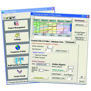
Once all the data is collected, the modeler creates the model space, detailing all the pipelines and HVAC systems and providing the requisite parameters associated with each of these elements. There are several commercially available AC modeling software packages that each have their own format for inputting the pipeline, transmission and environmental characteristics. Once the model has been built, it can take hours, days and in some cases weeks, of processing time to run simulations and for the model to provide the results of the simulation.
Evaluating the Model Results Against Established Criteria
The results of the initial model run need to be evaluated against the criteria that is established by the pipeline owner. In the absence of specific guidance from the owner, MATCOR’s default criteria are:
- No more than 20 A/m2 AC current density for mitigating AC corrosion during steady state induced AC current
- 3000 volts maximum coating stress during fault conditions for newer FBE type coated pipelines in accordance with NACE standard SP0177-2014
- 15 VAC for step and touch potentials at above ground appurtenances
For any given application, one or more of these criteria may be exceeded along the model’s area of analysis.
Adding AC Mitigation and Reevaluating the Modeling Results
Once the initial unmitigated results have been evaluated against the criteria that has been established, the modeler then adds, based on their experience with these systems, a mitigation scheme to the model with grounding at selected locations. This is often an iterative project where the model is run and the results evaluated and then if necessary, additional mitigation can be added or excess mitigation can be removed and the model rerun again in search of an “optimized” modeling solution that addresses all of the threats and results in meeting the requisite criteria.
Final Report
Once the AC modeling effort has developed a solution, the modeler develops a final report. Typical components of a final report include an introduction detailing the scope of the study, graphical illustrations of the pipeline(s) and transmission line(s) overlaid onto a satellite image, description of the modeling software used, detailed graphs/charts showing the results of the modeling, detailed drawings and bill of materials for the AC mitigation solution being recommended and appendices with the underlaying data.
Summary
AC Interference issues can be quite complex and modeling often offers the only valid way to assess and mitigate the risks from AC faults and steady state induced currents. When considering AC modeling it is important to look at the model being used and the modeler performing the evaluation.
Learn about our AC modeling and mitigation solutions:
Questions about AC interference, modeling or mitigation? Please contact us at the link below. Our experts are happy to help.
Contact a Corrosion ExpertAdditional Related Content
- AC Interference Video: Basic Theory
- AC Mitigation: 4 Approaches
- The MITIGATOR® Engineered AC Mitigation System
- Engineering Report: Comparison of 3 AC Mitigation Methods (MITIGATOR, bare copper and zinc ribbon anode)


