AC Corrosion Implications for New and Existing Pipelines
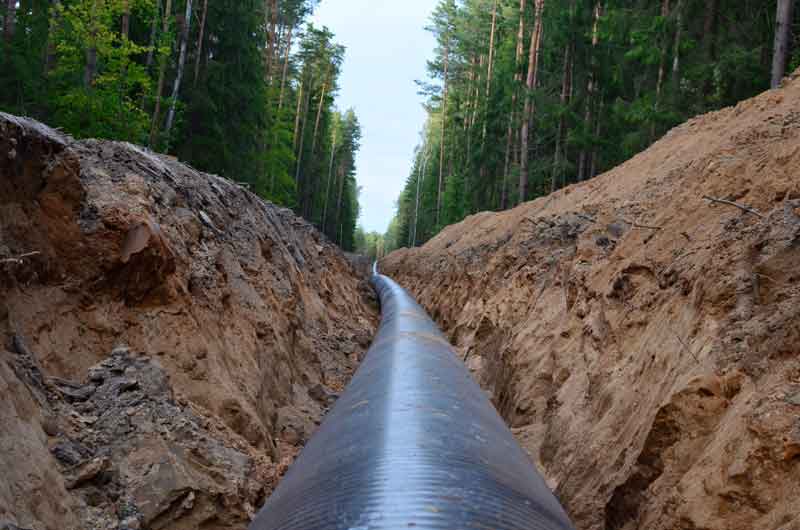
AC inference can result in significant and rapid corrosion and is a threat that must be considered for both new and existing pipelines. NACE provides a detailed standard practice to specifically address the threat of AC corrosion; however, it is very important for corrosion professionals to understand the guidelines and their implication for pipeline design, monitoring and risk assessment.
Criteria for Control of AC Corrosion
Approved in December of 2017, NACE SP21424-2018-SG “Alternating Current Corrosion on Cathodically Protected Pipelines: Risk Assessment, Mitigation, and Monitoring” provides supplemental guidance for the control of corrosion for cathodically protected pipelines that are subject to influence from close proximity high voltage AC transmission systems. This standard practice expands significantly on the earlier standard SP0177 “Mitigation of Alternating Current and Lightning Effect on Metallic Structure and Corrosion Control Systems” and introduces new criteria for addressing AC Interference for cathodically protected pipelines.
The criteria detailed in Section 6 of SP21424 allow for two means of assuring that effective AC corrosion control has been achieved:
- Document that the corrosion rate is less than the common benchmark for effective corrosion control of 0.025mm/y (1 mil per year). This can be achieved using weight loss coupons, corrosion rate probes or through in-line metal loss inspection tools—provided the inspection tool resolution is sufficient to detect small-diameter attacks such as AC corrosion. This approach is great for areas where AC corrosion risk is considered minimal. Essentially this says we don’t expect AC corrosion and we will demonstrate that AC corrosion is not occurring with a modest testing program. In those areas where AC corrosion can be reasonably anticipated; however, a second criteria is provided.
- For areas where AC corrosion mitigation can be anticipated, the criteria for effective control is based on reducing the time weighted average AC current density below a specific threshold that varies depending on the DC cathodic protection current density as follows:
- Where the DC current density is controlled to less than 1A/m2, the AC current density should be controlled to less than 100 A/m2
- Where the DC current density is not controlled to less than 1A/m2, the AC current density should be controlled to less than 30 A/m2
This first criteria, much like the first criteria for cathodic protection in SP0169-2013, allows for a prove-it type criteria based on documenting that corrosion is not occurring.
The second criteria, unlike the criteria for cathodic protection, is not based on a measured potential, but is instead based on measuring current density on a time weighted basis. Not just one type of current density must be considered, but instead the criteria requires evaluation of the time weighted average of both AC and DC current densities.
Current Density vs. Polarization
While conventional criteria associated with control of corrosion through the application of cathodic protection is based on shifting potentials on the pipeline, the control of AC induced corrosion is based on limiting current density criteria on a time weighted basis. These requirements are quite different—and when AC corrosion control is a concern this will require a change in how pipelines are monitored, a shift in CP design philosophy in those areas where AC corrosion is a concern and some understanding of the impact of AC mitigation.
Pipeline Monitoring
Pipelines are typically designed to monitor polarization levels with the installation of test stations at frequent intervals to support measuring polarization levels at the test station and to facilitate continuous close interval polarization surveys. When AC corrosion is a threat, the monitoring provisions need to shift from providing connections to the pipeline for polarization measurements to the installation of coupon test stations to facilitate current density measurements.
CP System Design Philosophy
The primary concern with cathodic protection design is typically making sure that more than enough current is available to ensure minimum polarization levels (either 100mV shift or -850mV off potential) are met along the length of the pipeline. This often means the CP system is over-designed and overdriven—there is little cost associated with over-polarizing some segments of the pipeline to ensure that the entire pipeline meets the minimum requirements. If the pipeline does not meet criteria in some locations, the first step was to push more current over the entire system until those low potential sections also met the polarization criteria. Little consideration is given to concerns with areas receiving too much current.
However, when we overlay the concerns with AC induced corrosion and the desire to control the DC current density below 1A/m2 or face the requirement to mitigate to a much lower threshold for AC current density, it becomes a more challenging CP system design. Now the CP system designer must:
- Understand the interaction between cathodic protection system design and its impact on AC mitigation requirements
- Provide provisions to monitor (on a time-weighted basis) both AC and DC current densities
- Give consideration to being able to intentionally control DC current densities in those AC corrosion risk corridors—this might require additional CP stations to reduce over-polarization, the strategic use of isolation devices to create DC current density control zones, and the use of auto-controlled rectifiers to vary current output to control DC current densities. Improving the control of DC current density can significantly reduce the amount of AC mitigation that might be required.
AC Mitigation
For existing pipelines, the AC mitigation requirements should be based on some actual data on the CP current density in specific areas of concern. Current densities are typically highest closer to a CP station and in areas of low soil resistance. Another factor that can impact current density is the quality of the coating. Poorly coated pipelines have more uniform and lower CP current densities while well coated pipelines may have higher localized current densities because of the small size and infrequent nature of the coating defects. For new pipelines, the AC mitigation designer should be careful to presume that the higher AC mitigation threshold based on controlling DC current density can be applied without consultation with the CP system designer to assure that the design provides for sufficient control of CP current density.
Coupons
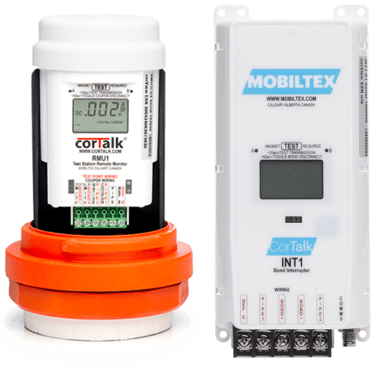
The use of AC test stations with specific AC and DC current density coupons is necessary to ensure that localized conditions do not exist where AC corrosion risk is not properly being controlled. These coupon test stations should be equipped with remote monitoring to allow for data polling at regular intervals to allow for time-weighted averaging of the current density data. Mobiltex recently introduced a new series of Test Station RMUs specifically designed to be installed in a conventional cathodic protection test station. These remote monitoring units can record and transmit AC and DC current density information from AC coupon test stations.
The frequency and location of these coupon test stations is a design issue. It is critical to note that within areas subject to AC corrosion risk, coupon test stations should be installed at all significant “inflection” points where predictive modeling and/or AC mitigation design experience would dictate elevated risk including:
- Entrance/exit points for HVAC / pipeline collocations
- Low soil resistivity areas or areas with notable differential soil resistivity changes within the collocation
- HVAC phase transpositions
- Pipeline crossovers
Conclusions
The criteria for AC corrosion control are different than those typically associated with conventional cathodic protection to control corrosion. The requirements for monitoring both AC and DC current densities are interrelated and can have a significant impact on the AC mitigation requirements and on the cathodic protection system design and operation. Understanding this relationship between AC and DC current density and properly controlling each is critical to properly controlling AC corrosion risk.
For information on MATCOR’s AC mitigation solutions or for assistance setting up testing to prevent AC corrosion, please contact us at the link below.

