In this video training session we talk about AC modeling. The summary below includes video timeline indicators so you can easily find your topic of interest in the video.
In the previous AC Interference video we talked about the effects of AC interference from transmission lines on parallel pipelines. We discussed three different modes of impact:
AC Interference Recap—3 Issues (0:24)
- Step and touch potential-must be below 50 volts AC
- Conductive coupling where a fault condition dumps current into the earth, causing potential damage to the pipeline
- AC induced voltage from the transmission lines on the pipeline
AC Modeling and Design
Best Guess Approach (0:57)
In some cases you can do a best guess AC mitigation approach, where it might not be worth the effort to put data and information into a model to determine the impact of AC interference on the pipeline.
Example: You have a simple application where you have one mile of pipeline collocated with high voltage transmission lines. You have measured that you’re picking up AC and decide that you’re going to put grounding in from point A to point B and be done with it. It is over-designed, but the cost of AC modeling would exceed the cost of this simple solution. This approach is based on experience in the field.
Complex Pipeline Arrangements Require AC Modeling (1:42)
When you get into more complex pipeline arrangements—multiple pipelines in the same corridor, multiple AC transmission lines coming in and out, multiple towers and circuits—you cannot just throw grounding in the earth and hope it is going to work. You may ground it in one location, and it may push the current somewhere else. In these cases you need to consider AC modeling.
AC Interference Modeling (2:08)
AC modeling is data intensive. And just like any model where we use a computer to predict what’s going to happen, the quality of the data impacts the quality of the results.
At MATCOR, we use a program called Right-of-Way Pro, a software package developed by Safe Engineering Services and Technology out of Canada. It is the leading AC modeling software available today. There are other packages that are less expensive and less accurate, but Right-of-Way Pro is the gold standard for AC modeling software.
AC modeling is a service that MATCOR provides. We have trained professionals with years of experience modeling AC systems in the pipeline industry, and experience with this complex software.
AC Modeling Goals (3:16)
The goals when you’re performing AC modeling are simple:
First, we calculate the fault condition stress values.
What is the worst fault condition that can occur? What is the worst that can happen at each tower and how does that affect the pipeline given the relationship of the pipeline to that tower? How far away is it? How deep is it? What is the resistance in that location? We model every tower along that collocation.
Next, we calculate induced voltage.
This is the impact of having an electrical field with the pipeline running through it and picking up voltage. We model this for every collocation. This can get rather complex when you have multiple pipelines and multiple AC towers in the same corridor.
Then, we predict the AC current density along the length of the pipeline.
In the AC Interference video we talked about AC induced corrosion being a function of how much current is being discharged off small holidays. There is a certain threshold we do not want to exceed or we will be concerned about corrosion occurring.
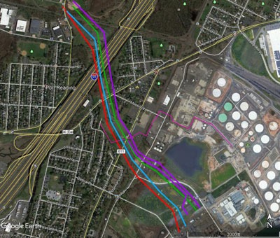
The model of the pipeline will show where it is picking up current. At every point along the pipeline, the model indicates, given a holiday of a certain size, whether we have a problem with AC corrosion. This will change depending on where we are along the pipeline collocation and what the soil resistivity is around the pipeline in that location. Lower soil resistivity tends to mean higher current discharge, and these tend to be the areas of concern.
Finally, we evaluate mitigation measures.
Where should we put mitigation, how much mitigation, and how effective will it be?
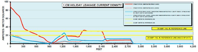
As we are calculating induced voltage along the length of the pipeline, we are looking for areas where we exceed 15 volts because this is a safety concern. We are also looking for areas where a 1 cm² holiday would have more than a maximum threshold of current density. 20 amps/M² is a typical threshold in the US, since that is where corrosion can occur.
AC Modeling Data Requirements (5:50)
We need a lot of data to build the model out, including data on the HVAC transmission line, the pipeline location and characteristics, and the soil resistivity. In addition, we need information about changes in the collocation relationship. These changes are called excitation points; if there is suddenly a change in the pipeline or the high voltage power line, it is often a hot spot in the system and where you will likely have problems.
HVAC Line Data (6:39)
For the HVAC line we want to know the tower geometry, which can change. How high are the towers? How long are the spans? What is the separation of the different phase conductors? AC is always a 3-phase system, with an A, B and a C line. We need to know if there are phase shifts and where they are located for the model. We also need to know the phase conductor arrangement, the conductor height and distances, if shield wire* exists, and current loading information. What is the average current flowing through that line? What is the maximum, or peak current expected? Is there anticipation that the rating will increase in the future? Finally, what are the fault and ground fault currents?
*Shield wire helps in fault conditions; if there is a fault, instead of dumping current to the earth it will travel along the shield wire.
(8:08) Collecting HVAC line data can be a challenge. It is often a combination of going out into the field and physically measuring, and contacting the power company to request information like maximum fault conditions, length of maximum fault, and how quickly will breakers trip to clear a fault. Power companies don’t always like to provide this information and will often ask operators, or consultants like MATCOR, to pay a fee. When this information is not available we sometimes make assumptions, however the more assumption we make the less valid the model becomes.
Pipeline Characteristics (9:12)
We want to know pipeline characteristics, which are generally easier to get. Either they are easier to measure or the pipeline company has good data already.
We need to know the pipeline diameter or diameters, as sometime this can change. A 16-inch pipe may become a 20-inch pipe at some location. This would be an excitation point because a change has occurred. What is the wall thickness and material? What is the coating type, thickness & quality? What is the coating conductance?
(9:52) If your pipeline has an older coating, you probably do not have a big AC problem. If you have a brand-new, high quality coating means you probably have a bigger AC problem.
Depth of cover survey—how does the pipeline change its depth relative to the earth? We need to know the accurate GPS centerline of the pipeline in addition to the location of valves, casings, bonds and foreign pipeline crossings. Finally we need to know soil resistivity at different depths and multiple locations along the pipeline. The AC modeling software has the ability to look at multiple layer effects of the soil.
All of this data must be collected and put into the model. Often the pipeline company can provide the data or we can go out and measure it.
AC Modeling Software Key Features (11:35)
- Up to five layers of soil resistivity modeling
- A large conductor database—including most transmission line conductors, all copper conductors and mitigation devices such as zinc ribbon and the MATCOR MITIGATOR®
- The ability to model large networks with multiple pipelines and multiple power lines along a corridor in the same model
AC Modeling Costs (12:11)
For a relatively simple collocation, you may not need to perform AC Modeling. A very simple AC modeling job might be $20,000. The cost can be well over $100,000 for a project requiring a lot of data collection and modeling effort.
In some cases it may be simpler to put in $10,000 worth of grounding and “overdesign” the AC mitigation system since the cost of modeling would be greater. In other cases, AC modeling is an absolute necessity.
AC Modeling Software Capabilities (12:42)
- Transformers, insulators, substations and other devices
- Different phasing, pipe diameters and coating type configurations in one model
- Solid state decoupler sizing
- 3-D viewing and plotting
- AC corrosion output
- Fault modeling
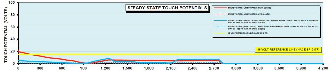
AC Modeling Software Output (13:42)
The output from the software shows you along the length of the pipeline, those areas where you have concerns about steady state touch potentials, from a safety standpoint where it might be above 15 volts.
It will also provide your 1 cm holiday leakage current density, indicating areas where you are at risk for AC induced corrosion.
In addition the software provides areas where fault currents can exceed the maximum allowable for your coating stress.
When is AC Modeling Not Required? (14:16)
- Simple applications
- When overdesigning AC mitigation solves the problem
In our next segment we will talk about AC mitigation. What do you do once you know where the problems are?


