This article explores the answer to a question posed by a student about the length of pipeline protected by a cathodic protection system.
We recently received a question from our website from someone who self-identified as a Student. We love when people ask technical questions and are pleased that students visit the MATCOR website–we have always strived to have a content-rich website to help share CP knowledge. The question is as follows:
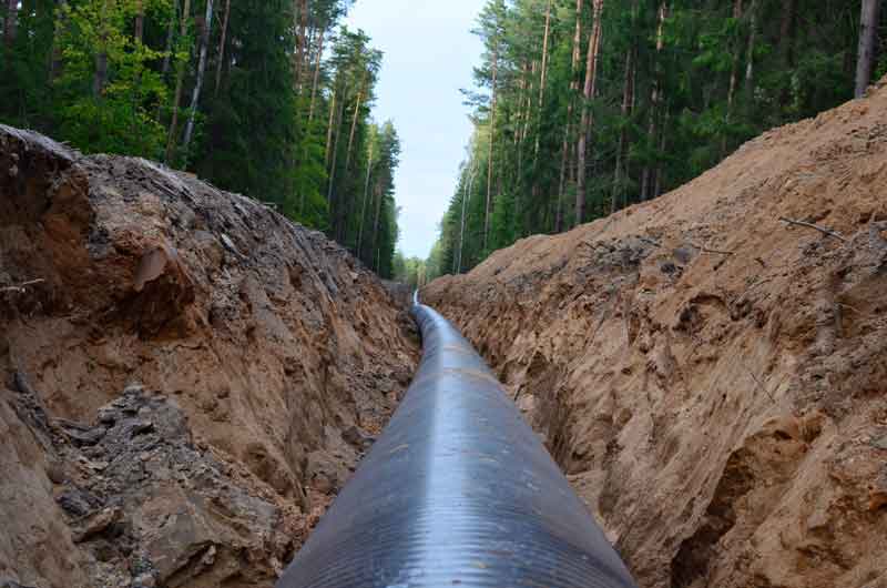
“For installed impressed current CP systems with 15 anodes, what would be the approximate radius/length of a 200-mile petroleum metal pipe that would be protected?”
So before diving into the answer, let’s frame this question with an assumption, identify some unknowns and provide a definition.
Assumption
The 15 anodes are part of a single anode bed. The anodes are electrically remote from the pipeline and connect to an appropriately-sized DC power supply (transformer/rectifier, solar power/battery unit, thermoelectric generator, etc.)
Unknown #1: Pipeline Details
Before doing any detailed engineering, there are a few details that must be specified:
- Pipeline diameter and material of construction
- Coating type and condition
- The layout of the pipeline (location of pumping stations, valve stations, and metering stations)
Unknown #2: Soil Conditions
Understanding soil resistivity in terms of location, frequency, and spacing, is critical when designing cathodic protection systems for long-length pipelines.
Definition of Attenuation
a lessening in amount, force, magnitude, or value according to Merriam-Webster
When discussing at what distance cathodic protection continues to be effective along a pipeline, you must consider the attenuation of the CP current. At some point, the current diminishes along the length of the pipeline, becomes insufficient, and can no longer protect the pipeline.
The Answer: Impressed Current CP Systems are Complicated
We can effectively use attenuation calculations for signals generated on a uniform conductor and transmitted through a uniform environment.
In this case, the pipeline is not a uniform conductor; unless it is bare, it is anything but uniform. The coating has less than perfect effectiveness and an unknown number of defects distributed in an unknown manner. The environment is equally non-uniform; soil resistivities change based on location and weather changes. The more non-uniformity, the more inaccurate the results will be for any attenuation calculations.
It is virtually impossible to model mathematically for older pipelines with insufficient coatings. The only effective strategy is to collect data by installing a temporary current source to measure the effective current throw in each direction in multiple locations along the pipeline.
For new pipelines with very good coatings, it is possible to perform some attenuation calculations and empirically determine a reasonable separation distance between anode stations.
The math starts with determining something called the propagation or attenuation constant. To calculate this, take the square root of the resistance per unit length of the structure divided by the leakage conductance per unit length.
In Simple Words…
How hard is it for the current to travel along the pipeline versus how easy it is for the current to jump onto the pipeline?
The smaller this number, the further current will spread. Key factors affecting the attenuation constant include earth resistivity (higher resistivity soils mean further current spread) and coating quality (better coating means further current spread). Armed with this, there are six simultaneous equations that we can use, and that include hyperbolic sine and cosine functions.
Larger, new construction pipeline projects require you to consult with a professional engineer. A brief newsletter article will not adequately cover the mathematical gymnastics involved. We did say that the math is complex.
Well-coated, newer pipelines in moderate to high-resistivity soils can typically be protected for 20+ miles in each direction from an anode bed. Poorly-coated or bare pipelines in low-resistivity soils may require anodes every quarter mile or less.
Need more information? Please contact us at the link below.