Pipeline cathodic protection design for new pipelines may appear to be a rather easy task for anyone with a basic understanding of cathodic protection. However, as with all design efforts there are a wide number of factors that need to be considered for a sound design that meets generally accepted industry practices.
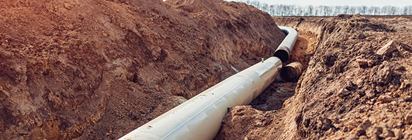
This article highlights 12 things that the pipeline cathodic protection system designer needs to consider when developing a CP system design. This is not intended to be a comprehensive list as every project has its own unique challenges, but these 12 items would all typically have to be addressed during the design phase. It is assumed that the basic pipeline information is already available to the CP designer including pipeline length, pipeline routing and pipeline characteristics (material, wall thickness, coating type, operating temperature, etc.). Armed with this basic information the CP designer should also consider the following in their design efforts.
12 Things to Consider for New Pipeline Cathodic Protection Design
- Soil Resistivity is a factor in many of the design calculations and assumptions (e.g. current requirement, anode resistance, attenuation, AC interference, etc…) Actual soil resistivity data should be collected along the proposed route. Learn about soil resistivity testing.
- Attenuation calculations should be performed in accordance with accepted industry standard equations and practice, such as NACE International CP-4 Cathodic Protection Specialist Course Manual 2000 Figure 2.18.
- Design current requirement is selected based on the soil type(s) using some accepted industry guidelines taking into consideration the coating manufacturer’s recommended coating efficiency or other industry accepted guidelines. Additional current requirements for mitigating interference currents should be considered based on the designer’s experience.
- Distribution of CP System Stations should take into consideration the total current required, the pipeline attenuation characteristics, the availability of power for impressed current cathodic protection systems, varying soil regimes, isolation valves and other factors to determine how many, what size and where each CP System will be located.
- Foreign pipelines and other DC interference sources should be evaluated as part of the CP system design efforts and generally warrant immediate mitigation measures or testing and monitoring provisions for observation and assessment.
- AC Interference assessment should be performed to determine if there are one or more high risk categories for AC Interference. Should the initial assessment confirm that there is potential for AC Interference an experienced AC Interference and Mitigation specialist would typically use sophisticated AC modeling to assess the risk and propose appropriate mitigation. From a CP perspective, there is a relationship between DC current density and AC induced corrosion risks where too much cathodic protection accelerates the AC induced corrosion rate so care must be exercised by the CP designer to avoid high DC current densities in AC risk areas.
- CP Station design includes the type of anode configuration, anode selection, installation methodology, etc… The CP designer will typically provide detailed Bill of Materials as well as CP System issued for construction drawings and construction details showing the location of equipment and providing installation instructions.
- Isolation of MLVs and Stations is a key design criterion that impacts the pipeline cathodic protection system design. Some owners are strongly in favor of isolation of MLVs and Stations from their main pipeline while other owners prefer not to isolate and have to maintain isolation and instead require the that CP system be sized to account for losses to current drains.
- Power supply type, sizing and selection is another of the decisions that is determined by the CP designer with consideration given to the pipeline owners specifications and preferences. For most pipeline applications, impressed current systems are typical and these require a DC power source. Electrical AC to DC power supplies (“rectifiers”) are the most common power supply but for remote areas with limited AC power availability, alternate power supplies such as solar, wind, fuel cells, thermo-electric generators or other sources may be required.
- Terminal piping is often associated with a new pipeline construction project and the pipeline CP system designer must often provide a supplemental design specifically for the terminal or station piping, or account for these in the primary pipeline CP system design
- Use of temporary CP systems is often recommended when permanent power may not be available for some time. These typically involve the installation of galvanic anodes strategically along the pipeline.
- Provisions for testing and monitoring are critical components to any successful pipeline CP system design. This often includes the use of remote monitoring systems for all of the system power supplies, specialized test coupons for AC and DC Interference, and numerous cathodic protection test stations placed at the appropriate strategic locations to be able to properly test and monitor the CP system performance.
As noted earlier, this is far from a comprehensive list of all of the factors for a specific pipeline CP System design. Every project may have its own unique challenges; however, the 12 items listed above represent a great starting point for any new pipeline cathodic protection system design challenge.

