MATCOR provides a full range of AC Mitigation capabilities including AC Modeling and Design engineering services, supply of our proprietary Mitigator® engineered AC grounding system, and an entire construction services organization capable of a wide range of AC Mitigation installation services. Two current projects highlight our construction service capabilities with regards to AC Mitigation. The first project involves several miles of zinc ribbon installation for an AC mitigation system in a congested suburban and urban environment using horizontal directional drilling (HDD) equipment. The second application is in a highly rocky environment in West Texas that requires the use of specialized rock trenching technology for zinc ribbon installation.
Zinc Ribbon Installation Using HDD in a Congested Environment
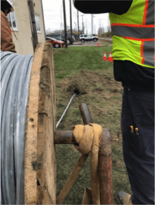
Figure 1 – Zinc ribbon being installed through HDD bore hole
This project in northwestern Ohio involved the zinc ribbon installation over several miles using one of MATCOR’s in-house horizontal directional drilling crews. The project required horizontal directional drilling to minimize surface disturbances due to the congested area.
With any typical AC Mitigation installation there are numerous precautions that must be taken to assure a safe installation. This starts with a thorough pre-construction safety review to develop the project site-specific health and safety plan. Each crew member participates in a daily safety meeting to review the day’s planned activities and address all safety concerns in advance of performing any work. Each crew member is required to have the appropriate operator qualifications and site-specific safety training as identified by MATCOR and the pipeline owner.
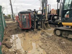
Figure 2 – HDD bore in process
Prior to any other construction activities, the first task is to perform a thorough line locating including potholing (excavation of the top of the pipe). This is to physically assure that the location of the pipeline(s) being mitigated is accurately marked to avoid any risks associated with construction activities in close proximity to the pipeline.
Once the pipeline has been physically located and properly flagged, each individual bore must be planned. The route of the bore is assessed prior to boring activities commencing. The bore planning includes:
Identifying entry and exit points
How the bore is to be tracked
Special precautions that might be needed to maintain the bore during the ribbon installations
How the cuttings will be captured, stored and removed
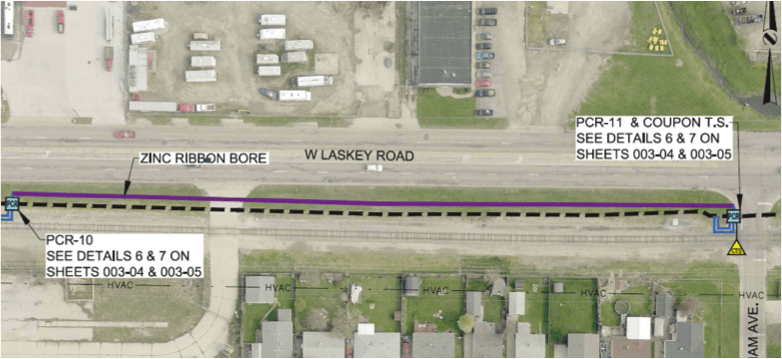
Figure 3 – Zinc Ribbon Bore – AC Mitigation design detail – note rail line to the South
As with any construction project, logistics and project management are key to the successful execution of the project. Working in conjunction with the owner and their designated project inspector to assure that the work is performed safely and in accordance with the AC Mitigation design requirements. For the project in Ohio, some additional complications included difficult weather conditions and working in close proximity to a railroad which requires additional permitting and coordination with the railroad. In some locations, traffic control was also required during the installation work.
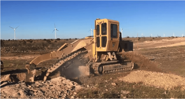
Rocky Conditions in West Texas
Figure 4 – Rock trenching in a difficult West Texas environment
Another project that MATCOR is currently completing involves the installation of approximately 15 miles of zinc ribbon in West Texas. The original installation plan called for the use of a cable plow to install the zinc ribbon mitigation wire; however, for large stretches of the installation, the rocky conditions forced MATCOR to switch from the planned cable plow to a high-powered rock trencher to cut through the difficult rocky terrain. This project illustrates the importance of using the right equipment to overcome difficult installation challenges. In some cases, being able to adapt to adverse conditions requires a change in construction methodologies and for this project, MATCOR’s ability to react and make equipment changes allowed the project to proceed on schedule with minimal customer impact.
This project also requires the use of HDD for one specific mitigation segment, as the pipeline traverses a cotton field which includes a buried drip irrigation system. The use of HDD is required to prevent any damage to the drip irrigation system during the AC Mitigation zinc ribbon installation. Coordinating the installation schedule around the cotton crop cultivation added another logistical challenge to the project.
Whatever your AC Mitigation challenge might be, MATCOR’s construction teams are able to work with our clients and their project needs to assure a safe and cost-effective installation project.
Have questions about zinc ribbon installation, or need a quote for AC mitigation materials or services? Contact us at the link below.
Engineers rely on soil resistivity testing as one of the most critical steps in designing an effective cathodic protection system. This soil resistivity test method provides the data needed to evaluate soil conditions and design reliable corrosion protection systems.
Accurate soil resistivity data directly impacts the anode selection, system performance, and long-term corrosion control. Incomplete or inaccurate data leads to underperforming systems, premature failure, and costly redesigns.
It also serves as a foundational input to cathodic protection design, helping engineers develop systems based on accurate field data.
This article explains how engineers perform soil resistivity testing, when they need it, and how the data supports real-world cathodic protection design decisions.
What is Soil Resistivity Testing and Why It Matters for CP Design
One of the most important design parameters when considering the application of cathodic protection for buried structures is the resistivity of the soil. Engineers use soil resistivity testing to assess the corrosivity of the environment surrounding buried structures.
Soil conditions directly influence:
System type
Anode quantity
System configuration
Without accurate soil resistivity data at both the structure and proposed anode locations, engineers risk designing ineffective cathodic protection systems that require costly remediation after commissioning.
How Soil Resistivity Determines Soil Corrosivity
Soil resistivity is the primary diagnostic factor for evaluating soil corrosivity. When engineers perform soil resistivity testing, they also consider factors such as:
Soil composition
Moisture content
pH
Chloride and sulfate concentrations
Redox (oxidation-reduction) potential
While comprehensive soil analysis may be required for failure investigations, soil resistivity testing provides the most practical and widely used field measurement for cathodic protection design.
Soil Resistivity Ranges and Corrosivity Classification
Below is a typical chart correlating soil resistivity with soil corrosivity.
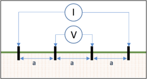
While there are several methods for measuring soil resistivity, the most common field testing method is the Wenner four-pin method (ASTM G57).
This method uses four metal probes, driven into the ground and spaced equidistant from each other. The outer pins are connected to a current source (I) and the inner pins are connected to a volt meter (V) as shown in Figure 1.
Soil Resistivity Formula and Calculation
Engineers convert measured resistance (R) into resistivity using a standard soil resistivity testing formula:
ρ=2×π×ax 30.48 cm/ft. ×R = 191.5 x a x R
Where:
ρ = soil resistivity, Ω-cm
a = probe spacing, ft.
R = measured resistance, Ω
How Probe Spacing Relates to Testing Depth
Each probe spacing represents the average soil resistivity to a depth equivalent to that spacing. For example, a 5-foot spacing reflects the average resistivity at approximately 5 foot deep.
For shallow anode placement, it is usually sufficient to take reading readings at 2.5 ft, 5 ft, 10 ft, 20 ft, 25 ft. For deep anode applications, soil resistivity measurements may be recommended at much deeper depths corresponding with the anticipated depth of the deep anode system.
Understanding Soil Layer Effects in Resistivity Testing
It is important to note that the soil resistivity values generated from the four pin testing represent the average soil resistivity from the earth surface down to the depth, and each subsequent probe spacing includes all of the shallow resistance readings above it.
Using the Barnes Method to Interpret Layered Soil Resistivity
To isolate resistivity at specific depths, engineers apply analytical techniques such as the Barnes method. This method:
Converts resistance to conductance
Evaluates incremental changes between readings
Calculates true layer resistivity
Engineers rely on this approach to identify low-resistivity zones that significantly impact cathodic protection performance.
Example of Layered Soil Analysis
For the Barnes analysis below, the data shows that a low resistance zone exists between 60m depth and 100m depth.
TEST DATA
BARNES ANALYSIS
Spacing a
(m)
Resistance
(ohms)
Conductance 1/R
(Siemens)
Change in Conductance
(Siemens)
Layer Resistance
(ohms)
Layer Resistivity
(Ohm-m)
20
1.21
0.83
—
1.21
152
40
0.90
1.11
0.28
3.57
441
60
0.63
1.59
0.48
2.08
264
80
0.11
9.09
7.5
0.13
17
100
0.065
15.38
6.29
0.16
20
120
0.058
17.24
1.86
0.54
68
Choosing the Right Soil Resistivity Testing Equipment
Engineers must use the right soil resistivity testing equipment to collect accurate field data. Electrical noise from power lines, substations, railroad tracks, and many other sources can distort readings if not properly managed.
Modern soil resistivity meters include filtering capabilities to reduce interference and improve measurement accuracy.
High-Frequency Soil Resistivity Meters for Shallow Testing
High-frequency meters operate above 60 Hz and should be limited to data collection of about 100 feet in depth.
This is because they lack sufficient voltage to handle long traverses and they induce noise voltage in the potential leads which cannot be filtered out as the soil resistivity decreases and the probe spacing increases.
Engineers commonly use these meters for:
Shallow testing
Corrosion assessment
Shallow anode design
They offer a cost-effective solution but have limitations in deeper applications.
Low-Frequency Soil Resistivity Meters for Deep Testing
Low-frequency meters operate between 0.5 to 2.0 Hz and support deeper soil resistivity testing.
These meters:
Handle large probe spacing
Provide superior noise filtering
Deliver accurate readings at greater depths
Engineers typically prefer low-frequency meters for deep anode cathodic protection design.
Field Best Practices for Accurate Soil Resistivity Testing
Accurate soil resistivity testing depends on proper field procedures and site conditions.
Select the Right Testing Location. The use of the Wenner four pin testing method requires sufficient open area to properly space the pins to collect data to the depths necessary. For deep anode cathodic protection systems this would require a minimum of three times the anticipated anode system depth.
Avoid Interference from Buried Piping and Other Metallic Objects. The presence of any buried metallic structures (piping, conduit, reinforced concrete structures, grounding systems, etc…) provides low current paths that could cause a short-cutting effect that would distort the resistance readings and yield an erroneous soil resistivity reading.
Control Probe Depth for Accurate Readings. It is important that the probes are properly inserted into the earth. For shallow resistivity readings, probes that are driven too deep can impact the shallow readings. Ideally, the pins should be no deeper than 1/20th of the spacing between the pins and no more than 10 cm (4 inches) deep.
Minimize Electrical Noise During Testing. Soil testing should not be performed directly under high voltage transmission systems or near other outside sources of current in the soil such as DC light rail systems.
Record Soil Conditions and Environmental Factors. It is important that the location of the testing is accurately recorded along with the soil conditions and temperature at the time of testing. Testing should not be performed in frozen soil, or during periods of extreme drought or abnormally wet conditions.
When to Use Professional Soil Resistivity Testing Services
Professional soil resistivity testing for cathodic protection becomes critical when projects require accurate field data to support system design, deep anode installations, or corrosion troubleshooting.
Engineers rely on experienced providers to perform soil resistivity tests, interpret layered soil conditions, and deliver reliable data for CP design.
Working with a qualified team helps:
Reduce design risk
Improve system performance
Avoid costly rework
Key Takeaways: Soil Resistivity Testing for CP Design
Soil resistivity testing provides the most reliable indicator of soil corrosivity for buried structures and plays a critical role in cathodic protection system design.
Engineers most commonly use the Wenner four pin method to perform soil resistivity tests. When properly collected and interpreted, teams can design CP systems that perform reliably and efficiently.
 It also serves as a foundational input to cathodic protection design, helping engineers develop systems based on accurate field data.