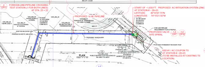
 This case study highlights some of the challenges associated with choosing AC mitigation design criterion for a new pipeline construction project. The specific project consisted of approximately 200 miles of pipeline with another 35 miles of lateral lines and included compressor stations, metering valves and a valve station. The final approved right of way consisted of 41 identified transmission lines spanning 5 different utility owners. MATCOR’s scope of work included designing both the CP system and modeling and designing an AC Mitigation system to address the extensive HVAC colocations.
For the AC Mitigation effort, MATCOR performed extensive field data collection along the right of way and MATCOR sent requests for utility operating data for AC Mitigation Design purposes. After 6 months of requests from the various utilities, the results were inconsistent with some utilities providing only emergency and peak data, others provided seasonal average data and one utility would not provide any data. Ultimately, modeling was performed based on actual data wherever possible, supplemented by assumptions based on experience from other AC Mitigation designs projects.
While this engineering project was being started, NACE was adopting its latest version of SP 21424-2018-SG “Alternating Current Corrosion on Cathodically Protected Pipelines: Risk Assessment, Mitigation, and Monitoring”. This latest version presented an updated criteria standard based on DC Current Density. Basically, if you can assure that the CP Current Density along the length of pipeline is controlled to below 1 A/m2 then you can tolerate a much higher AC Current density threshold of 100 A/m2 requiring less AC mitigation. If you are unable to control CP Current to the 1 A/m2 level, then the acceptable AC current density drops to a much lower 30 A/m2 threshold often requiring more extensive mitigation.
For the initial AC modeling effort, MATCOR based the AC Current Density limit to the lower, more stringent, 30 A/m2 criteria that assumes that the CP Current Density could not be controlled to below 1 A/m2. The modeling, given all the assumptions that we had to make, came back with:
- Numerous locations where Step and Touch Potential concerns required mitigation
- No concerns over fault current given the separation distances and fault currents presumed
- A very significant mitigation requirement to bring the induced current densities below the 30 A/m2 criteria including approximately 81 miles of parallel mitigation and 8 x 600ft deep grounding wells.
These results warranted additional review given the extensive AC Mitigation requirements from the initial modeling.
After some sensitivity assessments, a second modeling effort would be taken based on some revisions to the HVAC operating data based on updated information and some revisions to the input assumptions. This new modeling effort would also be run using 50 A/m2 as the AC Current Density limit. Additionally, based on input from operations, it was determined that all deep grounding wells would be limited to 200 ft depth. The new modeling effort resulted in a significant reduction in AC Mitigation required eliminating almost 50 miles of parallel mitigation.
The dual modeling efforts showed that there were numerous locations that were only slightly above the 30 A/m2 threshold but below that of 50 A/m2. In those areas, the owner opted to install additional monitoring systems but forego the initial installation of AC Mitigation and instead focus on those higher risk AC Interference areas by installing AC Mitigation.
This case story highlights the role of AC mitigation design criterion selection and the complexity around the current criteria that correlates CP Current Density levels, which are not typically controlled, to the AC current design threshold to mitigate the induced corrosion AC Interference risk. With judicious design decisions and a healthy amount of monitoring systems, there is significant value in your modeling criteria.
To get in touch with our team of cathodic protection and AC mitigation experts for more information, to ask a question or get a quote, please click below. We will respond by phone or email within 24 hours. For immediate assistance, please call +1-215-348-2974.
Contact a Corrosion Expert Evan Savant,


