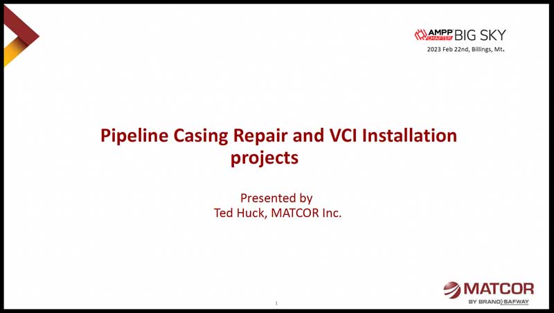
Recently, at the AMPP Association for Materials Protection and Performance Big Sky Section meeting, MATCOR’s Ted Huck presented a case study featuring the casing repair of a high-pressure natural gas pipeline running under railroad tracks and feeding into a power plant.
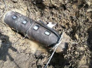
Following the repair, a vapor corrosion inhibitor (VCI) is installed to prevent corrosion.
Click on the presentation below to check out the development of a casing repair with VCI project scope, removing the short, sealing the casing, and installation of the VCI product through the vent pipe.
To get in touch with our team of cathodic protection and AC mitigation experts for more information, to ask a question, or get a quote, please click below. We will respond by phone or email within 24 hours. For immediate assistance, please call +1-215-348-2974.
In a recent MATCOR blog post, we discussed exothermic welding and pin brazing: Cathodic Protection Pipeline Connections: Exothermic Welding vs. Pin Brazing.
While the article focused on informing, we briefly discussed safety: “both methods are safe procedures when trained personnel follow the correct procedures.” This article will take a deeper dive into the safety considerations and procedures around making connections to pipelines using exothermic welding and pin brazing technologies.
Trained Personnel
Only trained personnel with sufficient experience should make connections to a pipeline. Therefore, short-service and inexperienced personnel should only perform this work if doing so under the direct supervision of an experienced person.
Daily Tailgate Safety Meeting
Note: Different organizations use different terminology, but the basic process is the same.
Every day the team plans and reviews various site activities. At this meeting, they review all applicable instructions, and identify, discuss, and document all potential safety hazards. Each team member signs the document to verify that they understand all safety concerns and their responsibilities.
Safety Hazards
Because pipeline connections are thermal, potential safety issues include flash, burns, accidental ignition, pipe burn-through, pipeline damage, inhalation risks (dust, smoke, ignition product, etc.), and eye injuries.
Therefore, safe entry conditions must exist before team members enter a pipeline or other structure excavation site.
Proper PPE
Personal Protective Equipment (PPE) is non-negotiable when performing pipeline connection work. All team members must:
Wear a hard hat and face shield to protect their head and face.
Wear safety glasses under their face shield with a 5.0 shade rating for pin brazing to protect the eyes.
Wear a particulate mask to protect yourself from grinding dust entering the lungs. Additional breathing protection equipment may be required to protect against inhalation of welding fumes in poorly ventilated areas.
Wear fire-resistant clothing to protect the torso, arms, and legs.
Wear leather gloves free of flammable or thin material to protect the hands.
Wear safety-toed leather boots (no rubber, neoprene, or other flammable materials) to protect the feet.
Positive Identification of the Pipeline
Before any physical work such as excavation, coating removal, heating, grinding, or welding on a pipeline or other structure, the project owner should approve the proposed work and work methods. This step includes positive identification of the pipeline or other asset(s) by the owner or owner’s representative.
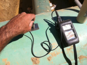
Air Monitoring
It is critical to monitor the air at the work site both initially and continually during the work with an LEL gas sensor.
Before proceeding, also test all flanged fittings and valves within 25 feet of the pipeline connection location should be tested with the gas sensor.
Thickness Measurement
Another critical safety step is for trained personnel to test the ultrasonic thickness of the area to be welded. The goal of this testing is to confirm that adequate wall thickness is present to prevent weld “burn-through.”
The table below details the minimum steel wall thicknesses as recommended by ERICO.
Record all results and compare them to nominal wall thickness. If the results indicate possible wall loss due to internal corrosion, the team must not proceed with exothermal welding.
Note: Do not perform exothermic welding if you measure a difference of 20% or more from nominal thickness or readings below 0.110” are measured.
Nominal Pipe Size
Schedule
Wall Thickness
0.5″
40
0.109″
0.75″
40
0.113″
1-2″
10
0.109″
2.5-4″
10
0.112″
5-10″
5
0.109″
10+”
5
> 0.109″
Coating Removal and Surface Profiling
Before coating removal, the pipeline operator should confirm that the coating is asbestos-free. Alternative removal procedures and safety precautions are required if the coating contains asbestos. A face shield should be used whenever grinding activities are performed.
Additional Considerations and Precautions
Explosive Internal Conditions
For active gas and liquids pipelines, the fluid velocity and lack of oxygen prevent the internal fluid from igniting due to the temperature rise in the pipeline wall. However, out-of-service lines are likely not fully purged, and oxygen and vapor may ignite inside the pipeline or vessel; purge these lines before proceeding.
Only perform exothermic welding on standard-thickness steel piping or vessels. Aluminum, copper, and thin-walled steel pose a greater risk of burn-through.
Don’t use anything larger than a 15-gram charge when welding onto steel fuel piping or vessels. Other structures, such as ductile iron pipes, may be more tolerant of more significant weld charges.
As you can see, both methods of pipeline connections are safe. However, adequately trained and experienced people must use the proper procedures and take the appropriate precautions.
To get in touch with our team of cathodic protection and AC mitigation experts for more information, to ask a question, or get a quote, please click below. We will respond by phone or email within 24 hours. For immediate assistance, please call +1-215-348-2974.
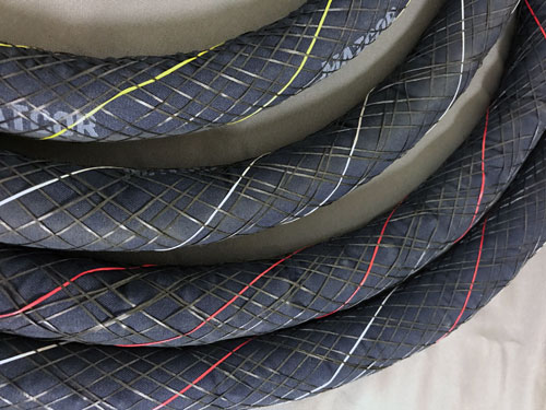
In February 2020, MATCOR revamped our SPL-FBR Linear Anode Product Line Offerings and introduced color coding for easy identification of different product ratings. Furthermore, MATCOR eliminated the 16 mA/ft, 50 mA/ft, 150 mA/ft, and 250 mA/ft from our standard offering. All of our SPL-FBR anode ratings are based on a 25-year continuous operation. The output ranges available are color-coded using different tracer wire coloring as shown in the chart below:
SPL-FBR Linear Anode Color Coding
CURRENT OUTPUT RATING
COLOR CODE
25 mA/ft
Yellow
100 mA/ft
White
200 mA/ft
Red
400 mA/ft
White and Red
MATCOR continues to offer, for specific projects or applications, custom anode output ratings on an as-needed basis.
MATCOR continues to be the world’s leading manufacturer of linear anode products, utilizing our patented Kynex® connection technology. With our product color coding, it is easier for our clients to identify the current output of their linear anodes.
To get in touch with our team of cathodic protection and AC mitigation experts for more information, to ask a question, or get a quote, please click below. We will respond by phone or email within 24 hours. For immediate assistance, please call +1-215-348-2974.
 In February 2020, MATCOR revamped our


