Matcor Earns Patent for Iron Gopher® Linear Anode

Iron Gopher® is only linear anode designed for cathodic protection in horizontal directional drilling applications

KENNESAW, Georgia, Sept. 19, 2018 — MATCOR, a BrandSafway company, recently earned a design patent for its Iron Gopher®, a linear anode designed to prevent corrosion through cathodic protection in horizontal directional drilling (HDD) applications. With a braided stainless steel jacket for linear anode protection during installation and a built-in pulling loop for connecting to the drilling head, the Iron Gopher provides approximately 200 percent more pulling strength than traditional anodes used in HDD applications.

It is available in standard and dual-end models, which can both be connected to a DC power source for active cathodic protection with a current. The standard model is used for most cathodic methods, such as roads, streams and property crossings, and the dual-end model is typically used under tank operations or anywhere it is not possible to connect both ends of the linear anode.

“We developed the Iron Gopher with installation costs and timelines at the forefront, focusing on strength to reduce the risks associated with the linear anode breaking during installation,” said Ted Huck, one of the Iron Gopher inventors and vice president of technical sales for MATCOR. “It also makes job sites—and utilities and pipelines—safer by using cathodic protection to decrease the chance of failure due to corrosion that could cause gas leaks or other potentially catastrophic events.”

The Iron Gopher was invented by Ted Huck; William Schutt, MATCOR founder; and Knut Fenner, former director of business development at MATCOR.

“MATCOR is an innovation leader in the corrosion and cathodic protection industry with its ongoing R&D, proprietary products, service and client-focused cloud technology,” Bob Burns, president of Midstream said. “The Iron Gopher is just another example of how we are continually raising the standards within the corrosion industry and ultimately providing the best solutions to our clients.”

For more information about Iron Gopher, visit www.matcor.com/products/matcor-iron-gopher.

About MATCOR

MATCOR, Inc. is a BrandSafway company and a leading cathodic protection and corrosion prevention engineering design firm, providing environmentally beneficial systems and services to global clients for more than 40 years. An ISO 9001:2015 certified expert in the field of cathodic protection, MATCOR offers proprietary corrosion protection design, engineering, manufacturing, installation, cathodic protection testing, annual surveys, maintenance and complete corrosion protection project management. MATCOR specializes in protecting the infrastructure of the oil and gas, utility, transportation and construction industries. To learn more about MATCOR, please visit www.matcor.com or call 1-215-348-2974.

About BrandSafway

With a commitment to safety as its foremost value, BrandSafway provides the broadest range of services, products and solutions, with the greatest depth of expertise, to the industrial, commercial and infrastructure markets. A portfolio company of Clayton, Dubilier & Rice, BrandSafway offers access, industrial services and forming and shoring solutions to more than 32,000 customers through a workforce of approximately 35,000 employees, who support our network of 350 strategic locations across 30 countries. With its global footprint, rigorous operating processes and extensive service offerings — a full range of work access, insulation, coatings, specialty industrial services and forming and shoring solutions — BrandSafway supports customers’ maintenance and refurbishment needs as well as new construction and expansion plans. Today’s BrandSafway — large enough to leverage economies of scale to increase safety and productivity, while also remaining nimble and responsive — delivers unmatched service with local labor and management.

AC Mitigation Video | Overview of Goals, Strategies and Materials

We’ve talked about AC Interference and we’ve talked about AC Modeling. The topic of our newest training video is AC Mitigation. The video is about 9 minutes long and we’ve included timeline indicators below so you can easily find your topic of interest in the video.

The goal for AC mitigation is to reduce your fault condition stress values to protect against stress coating damage and arcing potentials (arcing is less common because you need to be very close to the pipeline for arcs to appear). This includes:

  • Reducing current density below your threshold value. Typically in the US we use 20 amps per meter squared for a one CM2
  • Maintaining AC step and touch potential below 15 volts so that people working in and around pipeline areas are not subject to shock due to a fault condition

AC Modeling Aids in Predicting Conditions [0:55]

We use AC modeling to provide predictions and look at the mitigated and unmitigated conditions. Some cases warrant building a model, in other cases we can use “ad hoc” methods (such as experience) to come up with an effective AC mitigation plan.

Learn more in our AC Modeling Video.

AC Mitigation Schemes [1:14]

For our example pipeline application, AC modeling results show some locations to be concerned about where the 20 amps per square meter threshold is exceeded. These locations are indicated below, where the red line is above the yellow 20 amps per square meter reference line. What do we do to mitigate this risk?

AC Modeling Results

In this case, we’re going to put in a gradient control line in the areas of concern next to the pipe. This is a grounding system that attaches to the pipeline so that AC being picked up by the pipeline has a place to go. The coating system is “too good” with only a few small holidays, which means all of the current being picked up tries to rush out of those few small holidays. This is how you end up with AC induced pipeline corrosion.

By putting in a grounding system at strategic locations along the pipeline, we can reduce the AC voltage being picked by discharging it and giving it a place to go.

There are several ways to design an AC mitigation system but they are all basically grounding systems. Our solution in this case is shown as the blue line representing a grounding mitigation line.

AC Mitigation Grounding

Typical AC Mitigation Strategies [2:23]

  • Install a gradient control mat at locations where people can touch the pipeline
  • Maintain safe pipeline to power line separation distances to avoid arcing problems during fault conditions
  • If separation distances are too close, include a shield that picks up current as it is dumped to the earth and deflects away to protect the pipeline
  • Provide grounding of the pipe to the earth to dissipate current being picked up during steady-state conditions

What is a gradient control mat? [3:00]

A gradient control mat is a simple device that is connected to the pipeline to protect workers from step and touch potentials.

It is connected to the pipeline appurtenance where a person can touch the pipeline, and extends out enough so that somebody standing on it will not have that step and touch potential. Since it is connected to the pipeline, the entire gradient control mat has the same potential as the pipe.

As soon as I step on to that gradient control mat, I don’t have a voltage difference between me and everything else. Even if I touch the pipe, the ground below me is at the same voltage as the pipe, so no current flows through my hand, to my body and into the ground.

It is a fairly significant effort to install a gradient control mat but they protect people close to that appurtenance. Once they are above that gradient control mat, touching or being near the pipeline is not going to cause a problem. Current doesn’t flow unless there is a voltage difference. You can actually be in an environment where there is high voltage all around you, and as long as you are at the same potential (or equipotential), there is not going to be any current flow, and current is what can injure or kill you.

AC Mitigation Case Study [4:33]

In the case study shown, a pipeline runs parallel for 8 km to a transmission line, with the towers next to the pipeline. In this case the towers are too close so we use a zinc ribbon shield wire to protect from fault conditions. The zinc ribbon picks up the current and dissipates it before it can cause damage to the pipeline.

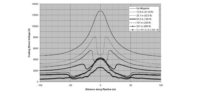
AC Mitigation Reduces Coating Stress Voltages

The chart below shows the effects without any mitigation, where you can see the voltage spike where it goes above 12000 volts of coating stress voltage.

Effects of Zinc Ribbon | AC Mitigation

You can see once various forms of mitigation are added, stress voltage drops below the limits. And depending on the type of coating, there’s a certain voltage limit that coating can withstand.

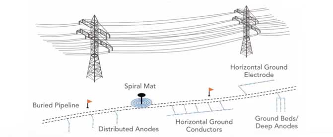
Pipeline Grounding Methods [5:46]

  • Spiral mat at pipeline valve stem location
  • Anodes in the earth that are connected to the pipeline; these become grounding rods for the pipeline
  • Horizontal ground conductors, connected at various lengths to the pipeline (gradient control line mitigation)
  • Deep anode ground beds


Deep Anode Case Study [6:25]

Deep anode ground beds are a little more expensive, however they a good solution in high resistance areas where you can’t discharge current into the ground effectively near the surface.

We did a project out west in the desert of the United States, where a new pipeline parallel to a transmission line was picking up AC voltage. In the very dry desert environment there was nowhere for this current to discharge. Grounding rods next to the pipeline do not work well in this case because the environment is so dry. We drilled holes 1000 feet into the earth and installed grounding cells. These were run up to the surface and connected to the pipeline to dissipate the AC voltage being picked up.


[7:11] There are a variety of ways to ground a pipeline; AC mitigation is basically how we ground the pipeline effectively.

AC Mitigation Materials [7:16]

The most common materials used for pipeline grounding include:

  • Zinc ribbon laid parallel to the pipeline
  • Bare copper, which is used predominantly in the corrosion industry
  • Engineered copper grounding systems; The MATCOR MITIGATOR® is an example of this type of system
  • Conducrete® systems where conductive concrete is used to enhance the earth’s surface area

AC Mitigation and Grounding Concerns [7:58]

  • Ease of installation
  • Performance
  • Life, how long is it going to last
  • Cost

Optimum AC mitigation [8:12]

  • The AC mitigation system is only as good as the modeling, so it is critical to ensure that modeling is accurate
  • Gradient control lines parallel to the pipeline are the most common grounding system used currently, although there are also quite a few locations using deep anode systems
  • For fault conditions, short lines at tower footings tend to be the most effective AC mitigation strategy

Have questions after viewing our AC mitigation video, or need a quote for AC mitigation materials or services? Contact us at the link below.

CONTACT A CORROSION EXPERT

Leak Detection and Repair

What is leak detection and repair (LDAR)?

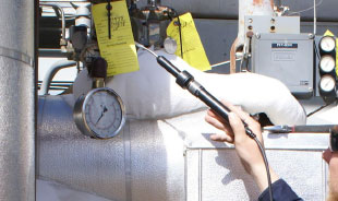
Leak Detection and Repair (LDAR) Programs are put in place to monitor process equipment leaks for fugitive emissions in the petrochemical industry. Solid LDAR programs are critical in controlling fugitive emissions of VOCs, or volatile organic compounds, that cause pollution and safety risks for facility workers and operators, and the environment.

LDAR - Leak Detection and Repair
Leak Detection and Repair (LDAR) Programs are put in place to monitor process equipment leaks for fugitive emissions in the petrochemical industry.

Maintaining refinery process equipment through an LDAR program mitigates these risks. Utilizing leak detection equipment to identify equipment leaks and then repairing those leaks in a timely manner enables operators to prevent most most fugitive emissions occurrences. In addition, successful leak detection and repair programs prevent product loss that impacts facility efficiencies and economics, the health and safety of workers, and the environment.

The article reviews fugitive emissions regulations and lays out a 5-step plan to build LDAR programs that accurately represent your project requirements.

Leak Detection and Repair Program Steps

Step 1: Develop Your Standard Operating Procedures

The first step in developing a successful leak detection and repair program is a cooperative endeavor between you and an LDAR expert to complete, approve and adopt your standard operating procedures (SOP).

Step 2: Laws Governing Your LDAR Program

In the second step, your LDAR team will research and share comprehensive knowledge of the permits, regulation(s), consolidation agreements, consent decrees, permit(s), and/or binding agreements governing your facility’s LDAR program.

Step 3: Your LDAR Unit Equipment Information Packet

In step three, your team will set up a database of regulations for each unit in your facility. The LDAR team funnels, filters, and identifies congestion overlap and applicable LDAR regulations of varying stringency into a condensed table called a Unit Equipment Information Packet. This is a comprehensive knowledge base for all who need to know more about the LDAR program on a unit-by-unit basis at the subject facility.

Step 4: Facility Process Flow Diagrams

In the fourth step, the LDAR team obtains your facility’s process flow diagrams (PFD’s), piping and instrument diagrams (P&ID’s), the P&ID abbreviations key, material balance sheets, and stream speciation data from the appropriate contact identified in your SOP in Step 1. Smart software is then utilized to highlight or color-code the P&ID’s according to stream state and service. Then the field review begins.

Step 5: Component Inventory Database and Monitoring

In the fifth step, detailed data is collected on a daily basis for affected components. The LDAR team reviews all affected components for accuracy and compliance, and perform necessary correction. All corrections are updated in the database. Monitoring commences as scheduled according to the applicable regulation set up in your LDAR Unit Equipment Information Packet in Step 2. Finally, we initiate a monthly QA/QC process to ensure ongoing compliance.

Many regulations and a lot of detailed data are involved in designing a best-in-class LDAR program to ensure regulatory compliance when it comes to fugitive emissions. It is critical to review all data reports with your facility’s operations and environmental department for understanding and acknowledgement of completion and ongoing compliance.


Why BrandSafway for LDAR Solutions?

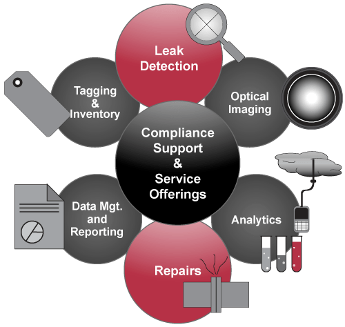
BrandSafway offers 150 years of management experience, cutting-edge technology and a highly effective data management system to ensure successful LDAR programs and more, while ensuring regulatory compliance with USEPA Method 21 and other mandated requirements for VOC monitoring.

LDAR Leak Detection and Repair Services

Learn about comprehensive LDAR Solutions from Brandsafway

MATCOR and BrandSafway are committed to being a valuable partner, providing a one-stop resource for industrial work solutions. By bringing together our expertise in both midstream and specialty services, we can better integrate and streamline asset and equipment management solutions for our customers in both the oil & gas and power markets.

Please click the link below to contact us if you have any questions about leak detection and repair, or if you’d like a quote for LDAR services.

Contact a Corrosion Expert
Get News from MATCOR

Sign Up for Our Newsletter

    I understand my information will be stored securely for the sole purpose of conducting business with MATCOR, Inc. I agree to receive future email communication and understand that I may opt out at any time. View our Privacy Policy.
  • This field is for validation purposes and should be left unchanged.