How MATCOR’s expert team completed a critical 20,000-foot mitigation project ahead of schedule—with zero incidents.
What is AC Mitigation and Why Does It Matter?
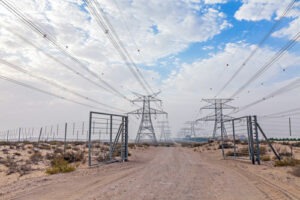
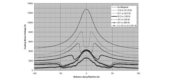
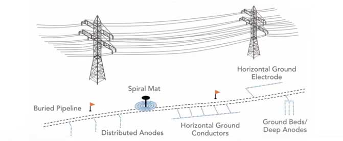
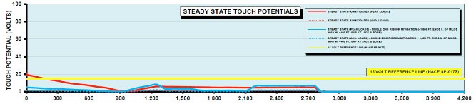
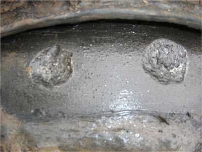
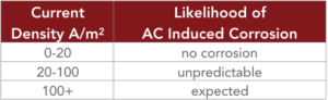
Pipelines that run near high-voltage AC transmission lines are at risk for electrical interference that can cause dangerous fault-induced voltage spikes, AC-induced corrosion, and personnel safety hazards from step and touch voltages. Traditionally, mitigation was installed manually using zinc ribbon—but technology has advanced.
“It used to be done manually with zinc ribbon. Now, with MATCOR’s trencher and spool system, it’s safer, faster, and more efficient,” Amanda explains.
Why AC Mitigation is Becoming More Urgent
AC mitigation is more than a compliance requirement—it’s becoming a strategic priority. The rapid expansion of high-voltage infrastructure to support massive new data centers and power plants across the U.S. is increasing the overlap between pipelines and transmission corridors.
“The race to AI dominance is fueling construction of data centers—huge energy consumers—which require new power plants and transmission lines,” noted Ted Huck. “That means more interference risks for existing pipelines.”
Even pipelines with recent mitigation studies in place can quickly become vulnerable. One operator saw significant interference issues just two years after mitigation—after a nearby fulfillment center and transmission line were added.
This trend is accelerating. Over the next five years, the U.S. is projected to build more than 250 power plants. That means more AC exposure, more co-located corridors, and a greater need for proactive mitigation strategies.
Want to dive deeper into this growing challenge? Read the full recap of Ted Huck’s presentation on “The Race to AI Supremacy and How it Threatens Our Pipelines” here.
Project Overview
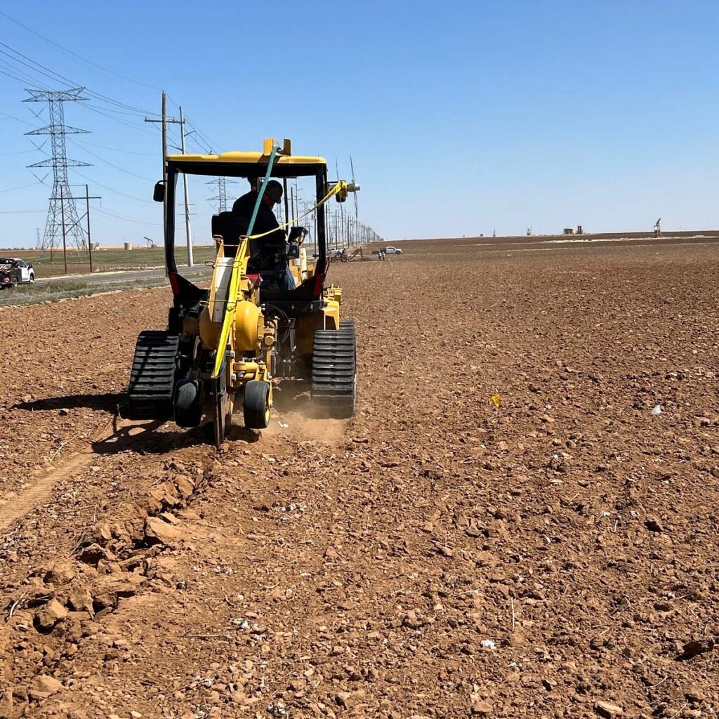
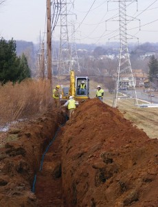
In early 2025, MATCOR was tasked with a major AC mitigation project by a longstanding pipeline operator in the West Texas region—an area rich in oil and gas infrastructure and notorious for its complex pipeline crossings. The operator had previously relied on zinc ribbon, and selected MATCOR’s Mitigator® for this installation.
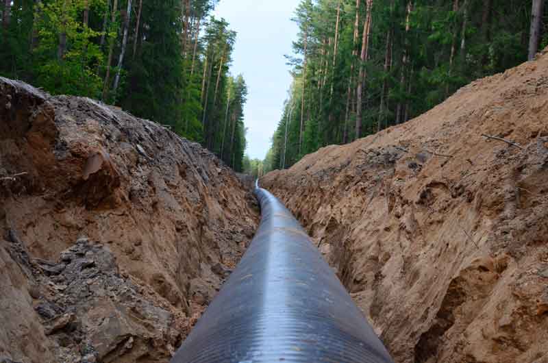
The job involved installing nearly 20,000 feet of Mitigator in challenging terrain, across farmland, and under tight deadlines.
For Amanda Miller, Project Manager at MATCOR, this was one of her first large-scale projects since joining the company. It also became one of the most rewarding.
“Everyone thought there’d be hiccups. But we finished 15 days early, and the customer was blown away.”
The Challenge
With only 32 days to complete the project—and landowner coordination, irrigation systems, and active pipeline crossings to navigate—everyone expected delays. But the MATCOR team delivered faster than anyone anticipated.
“We were able to complete the project in just 17 days thanks to strong planning, constant communication, and full team alignment,” Amanda said. “From the field crew to upper management, everyone came together.”
Why the Client Chose the Mitigator Over Zinc Ribbon
Although the client had previously used zinc ribbon for AC mitigation, they selected MATCOR’s Mitigator system for this project—marking a shift toward a more engineered, long-term solution.
The Mitigator is the industry’s only engineered grounding system designed specifically for AC mitigation. It combines high-performance materials with corrosion-inhibiting backfill in a sealed, ready-to-install package.
Key Benefits:
- 433% more surface area than bare copper
- Stranded copper conductor for superior electrical performance
- Corrosion-inhibiting backfill to extend system life
- Durable fabric wrap with heavy-duty braiding
- Low resistance to earth for effective grounding
- Ships on reels, ready for rapid installation
What Made It Work
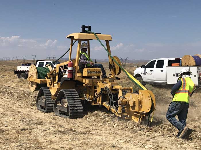
- All-in-one MATCOR crew: Unlike others in the field, MATCOR handled the full installation in-house. No subcontractors. No guesswork.
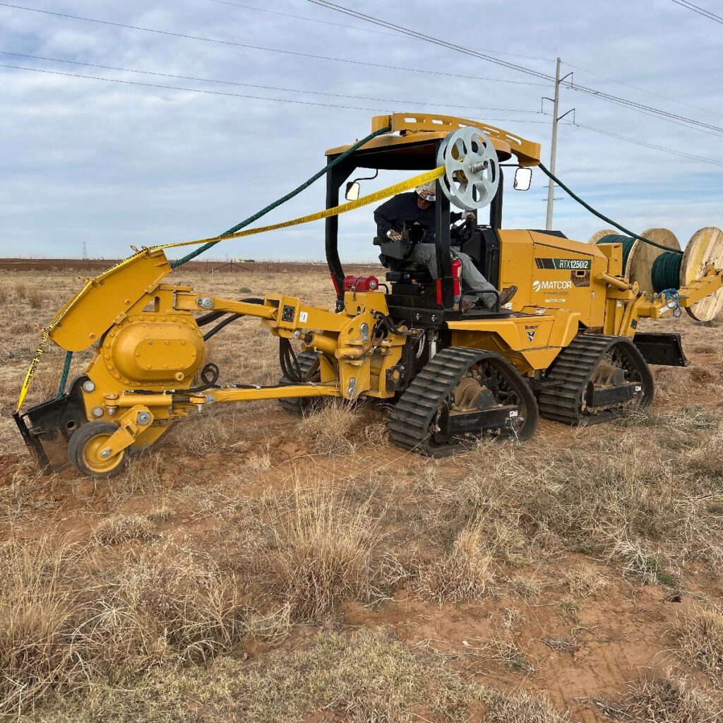
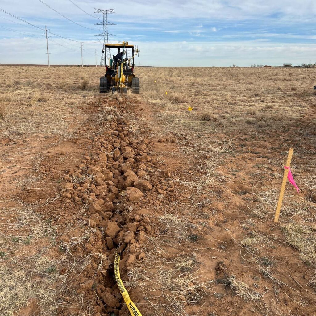
- Trencher + spool system: The Mitigator—designed and manufactured by MATCOR—was deployed using a specialized trencher that simultaneously laid the product and caution tape, streamlining the process.
- Client collaboration: Daily check-ins, a robust kickoff meeting with 15 client-side stakeholders, and real-time feedback helped build trust and showcase MATCOR’s commitment to safety and efficiency.
- Rapid problem-solving: Whether it was switching between CAD welding and pin brazing, sourcing cattle guards in under a week, or navigating high winds, every issue was solved within a day.
- Field mentorship: Josh Robertson led installation in the field while rotating crew members through training—passing on deep technical knowledge in real time.
Safety and Quality First
Despite the fast pace, safety was never compromised.
“We had high-level representatives on-site every day. They told us they couldn’t even tell we’d been there after 5,000 feet,” Amanda recalled. “That’s how clean and safe our work was.”
Results
- Project completed 15 days early
- Zero safety incidents
- No line strikes or utility hits
- Full client satisfaction and interest in additional projects
A Team Culture That Shows
Amanda credits the company’s leadership—Chuck Parrish, Brad Waters, Dennis Coldiron, and others—for creating a culture where everyone, regardless of level, supports each other.
“It’s the most supportive team I’ve ever worked with. From the top down, it’s never ‘not my job.’ It’s ‘how can I help?’ That made all the difference.”
Ready to Protect Your Pipeline with Proven AC Mitigation?
MATCOR’s industry-leading approach combines decades of expertise, purpose-built equipment, turnkey services, and a culture of safety and precision. Whether you’re in early planning or facing an urgent project deadline, we’re here to help you get it done—on time and with confidence.
Contact us today to talk through your next AC mitigation project.
Contact a Corrosion Expert