Impressed Current Sled Anode for Marine Structures
MATCOR is a leading manufacturer of impressed current sled anode systems and as such we tend to get asked a lot of questions about sled anodes. Here are some frequently asked questions:
Does it matter whether sled anodes are to be installed in seawater, brackish water or freshwater? What if the water salinity varies with the season or with tidal action?
These are two related questions, and both have to do with the conductivity (or resistivity which is merely the inverse of conductivity) of the water where the anodes will be located. The conductivity of the water plays a critical role in determining the overall system resistance and current output of the system. For freshwater locations, the relatively low water conductivity requires a significant quantity of anodes to keep the overall system resistance down. In those instances, a sled anode may not be the best design option as sled anodes are most cost effective in brackish or saltwater environments. For environments where the conductivity can vary seasonally or with the tides, such as estuaries or tidal river boundaries, special consideration may be required such as constant current or auto-potential controlled power supplies.
Why would we use impressed current sled anodes as opposed to galvanic anodes?
Depending on the application, there are compelling reasons for the use of each type of system. Galvanic anodes do not require an external power supply, are less subject to interference issues, and can be closely coupled directly to the structure. The impressed current sled anodes can greatly simplify installation, reduce overall costs, typically have a longer life, and can produce a lot more current from a lot fewer anodes. The choice of anode type is very much a site-specific consideration requiring a proper engineering evaluation during the design phase.
Are there any specific concerns with marine wildlife when evaluating cathodic protection systems?
Marine wildlife is generally unaffected by the presence of a cathodic protection system. Cathodic protection systems have been used in commercial aquariums and fish hatcheries without any impact on the marine life. At the structure, cathodic protection can result in a localized environment that reduces or inhibits the growth of barnacles while changes in the pH at the structure’s surface encourage the growth of calcareous deposits which reduce the current requirements and provide a form of protective coating for the steel structure.
The MATCOR sled anodes utilize a wooden base – are there any concerns with the deterioration of the wooden base releasing in chunks of wood that could damage intake structures?
We have not experienced any such problems – the wooden base is designed to sink into the mud along the sea floor and provide an anchor. Wood holds up very well in this environment; however, over time the wood will slowly become food for cellulose processing bacteria and eventually will slowly be degraded. This process is a natural process and occurs over a long period of time. There is no expectation that the wood base would break into pieces that could damage an intake structure. MATCOR can provide an inert non-metallic plastic base that would be like wood but not subject to natural biodegradation.
How do you protect the cabling from the Sled Anode back to the system rectifier?
MATCOR utilizes an HMWPE cable that has a very robust exterior jacket that is suitable for direct burial in soil or water environments. The cable is housed inside a 1” diameter flexible drilled PE pipe that provides mechanical protection for the cabling. We recommend the use of concrete weights to secure the cable along the seafloor. The drilled PE pipe holes facilitate the cabling sinking into the seafloor mud providing additional protection for the cabling.
What about dredging operations?
For locations that are subject to occasional periodic dredging operations every few years or so, MATCOR can provide a locator float and lifting lugs to allow for the anodes to be removed prior to dredging operations. If the frequency of the dredging operations is such that this would be a regular occurrence (multiple times per year), then consideration should be given to alternate designs that would not require anode removal on regular basis.
For information on MATCOR’s Sea-Bottom Marine Anode Sleds or for assistance with marine near shore cathodic protection system design, please contact us at the link below.
This is the time of year when thoughts turn to Thanksgiving and Christmas vacations, using up all your remaining vacation and wondering what to do with any leftover 2019 cathodic protection budget monies. More than likely, it is too late to schedule and complete new projects. MATCOR along with most of our competitors have full construction schedules and adding additional commitments is quite difficult.
Click HERE to get in touch with your MATCOR account manager for more information, to ask a question or get a quote. Or, complete our contact form at the link below and we will respond by phone or email within 24 hours. For immediate assistance, please call +1-215-348-2974.
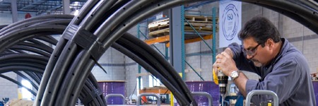
MATCOR is pleased to announce that we are now capable of performing Helium leak testing on our full range of linear anode products as an optional testing service. This is a common practice among companies and product developers that provide products that could potentially leak gas or that require water tightness. Products commonly leak tested include refrigeration lines, vehicle brake lines, and devices that contain potentially harmful or deadly substances. Helium is the second smallest element (Hydrogen is the smallest), which means that it is valuable for leak testing. Smaller molecules naturally can find smaller gaps or defects from which to leak. Unlike hydrogen, however, helium is a noble gas and is therefore unreactive due to its complete valence electron shell. As a result, helium is the most viable gas for use in leak testing.
Helium leak testing is now available for all MATCOR linear anodes, however our patented Kynex technology has zero reported failures since it was introduced a decade ago.
MATCOR has enjoyed an outstanding record as the world’s leading supplier of MMO anodes/Titanium linear anodes with over 25 years of linear anode experience supplying our industry leading SPL™ family of linear anode products for pipelines, tanks and other applications around the world. Our patented automated injection molded Kynex® connection technology has an outstanding track record with no known connection failures since this technology was introduced in 2009.
We do, however, see some client specifications calling for 100% connection testing and helium leak testing is the most effective means to test an entire anode assembly.
For more information, please feel free to contact your local MATCOR representative or contact us at the link below.
At MATCOR, we pride ourselves on being a world class manufacturer of unique cathodic protection systems and AC mitigation systems. Our anode systems offer you longer life, lower total installed cost, and are safer and easier to install than many conventional anode solutions. We have earned a reputation for exceptional manufacturing quality—but all companies say their products are world class and have exceptional quality, right? What makes MATCOR different? What does it mean to be exceptional?
At our state of the art Chalfont, Pennsylvania manufacturing facility we have developed a culture of quality. That is not to imply that we are perfect or that we don’t occasionally make a mistake; we are not perfect. However, we HAVE embraced, through our ISO Certified Quality Management System, a systematic approach towards excellence. So, while everyone aspires to do a quality job, our manufacturing team’s quality culture is based on perspiration—we work relentlessly to do a quality job for YOU by embracing the key tenets of quality.
Through our Manufacturing Quality Management System, we:
Document procedures for what we do
Train our team on the proper processes
Hold ourselves and our suppliers to high quality standards
Self-audit to ensure we are doing what we say we will do
Measure our performance daily through KPIs (key performance indicators)
Strive to continuously improve
Collect and act on YOUR feedback, comments and complaints
We’d love to hear from you about our manufacturing quality, please comment or contact us at the link below.
To get in touch with our team of cathodic protection experts for more information, to ask a question or get a quote, please click below. We will respond by phone or email within 24 hours. For immediate assistance, please call +1-215-348-2974.
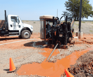
Iron Gopher® is only linear anode designed for cathodic protection in horizontal directional drilling applications
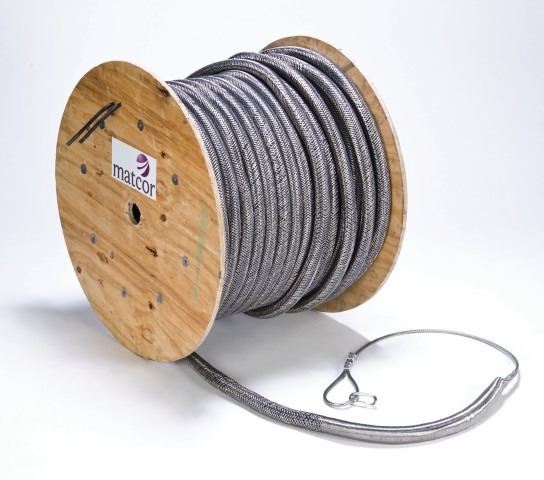
KENNESAW, Georgia, Sept. 19, 2018 — MATCOR, a BrandSafway company, recently earned a design patent for its Iron Gopher®, a linear anode designed to prevent corrosion through cathodic protection in horizontal directional drilling (HDD) applications. With a braided stainless steel jacket for linear anode protection during installation and a built-in pulling loop for connecting to the drilling head, the Iron Gopher provides approximately 200 percent more pulling strength than traditional anodes used in HDD applications.
It is available in standard and dual-end models, which can both be connected to a DC power source for active cathodic protection with a current. The standard model is used for most cathodic methods, such as roads, streams and property crossings, and the dual-end model is typically used under tank operations or anywhere it is not possible to connect both ends of the linear anode.
“We developed the Iron Gopher with installation costs and timelines at the forefront, focusing on strength to reduce the risks associated with the linear anode breaking during installation,” said Ted Huck, one of the Iron Gopher inventors and vice president of technical sales for MATCOR. “It also makes job sites—and utilities and pipelines—safer by using cathodic protection to decrease the chance of failure due to corrosion that could cause gas leaks or other potentially catastrophic events.”
The Iron Gopher was invented by Ted Huck; William Schutt, MATCOR founder; and Knut Fenner, former director of business development at MATCOR.
“MATCOR is an innovation leader in the corrosion and cathodic protection industry with its ongoing R&D, proprietary products, service and client-focused cloud technology,” Bob Burns, president of Midstream said. “The Iron Gopher is just another example of how we are continually raising the standards within the corrosion industry and ultimately providing the best solutions to our clients.”
MATCOR, Inc. is a BrandSafway company and a leading cathodic protection and corrosion prevention engineering design firm, providing environmentally beneficial systems and services to global clients for more than 40 years. An ISO 9001:2015 certified expert in the field of cathodic protection, MATCOR offers proprietary corrosion protection design, engineering, manufacturing, installation, cathodic protection testing, annual surveys, maintenance and complete corrosion protection project management. MATCOR specializes in protecting the infrastructure of the oil and gas, utility, transportation and construction industries. To learn more about MATCOR, please visit www.matcor.com or call 1-215-348-2974.
About BrandSafway
With a commitment to safety as its foremost value, BrandSafway provides the broadest range of services, products and solutions, with the greatest depth of expertise, to the industrial, commercial and infrastructure markets. A portfolio company of Clayton, Dubilier & Rice, BrandSafway offers access, industrial services and forming and shoring solutions to more than 32,000 customers through a workforce of approximately 35,000 employees, who support our network of 350 strategic locations across 30 countries. With its global footprint, rigorous operating processes and extensive service offerings — a full range of work access, insulation, coatings, specialty industrial services and forming and shoring solutions — BrandSafway supports customers’ maintenance and refurbishment needs as well as new construction and expansion plans. Today’s BrandSafway — large enough to leverage economies of scale to increase safety and productivity, while also remaining nimble and responsive — delivers unmatched service with local labor and management.
We appreciate the question: “How does soil resistivity impact current rating.” The short answer is that resistance has nothing to do with anode rating. Here is a more detailed response:
Anode current rating – all anodes have a current rating based on how long they can be expected to operate at a given current rating. All anodes have some defined expected life based on current output and time – so many Amp-Hours of service life. For example a magnesium anode may have an expected consumption rate of 17 lb/Amp-year (7.8 kg/amp) so if a 17 lb anode is operated at 0.1 amps it would have a life of 10 years. For MMO anodes, they too have an expected life. For our linear anode rated at 51 mA/m it is important to know that that rating is actually 51 mA/m for 25 years. So a 100m anode segment with this rating would have an expected life of 127.5 Amp-years. If this anode were operated at 5.1 amps (full rated capacity) it would be expected to operate for 25 years. IF it were operated at 2.55 amps (50% of rated capacity) it should last 50 years. The anode life is generally linear. Please note that resistance has nothing to do with the anode current rating – the anode current rating merely calculates the life of the anode as a function of how many amps for how long of time.
Actual current output – just because you install an anode rated for 5.1 amps for 25 years (our 100m segment of 51 mA/m SPL-FBR) does not mean that the anode will output this amount of current. It just means that at that current rating you can expect 25 years of life. The anode is merely one component of the overall cathodic protection circuit. The actual output of the anode is function of Ohms Law ( Voltage = Current * Resistance). It would make sense to note that if the system Voltage were zero (the rectifier were turned off or disconnected) then the anode would not have any current output. Likewise if the 100m anode segment were installed in a very low resistance environment and driven by a powerful rectifier, the current could be much higher than 5.1 amps which would result in a much shorter life.
Why anode rating is important to the CP designer – the CP designer is tasked with protecting a specific structure for a given period of time (protect this pipeline for 30 years.) The CP designer then calculates, based on actual testing or established guidelines, the amount of current that should be sufficient to achieve appropriate CP levels to protect the structure. This results in an answer of some number X of amps required. If the requirements are to protect the structure for Y number of years, then the anode life required is X * Y (# of amps times # of years). This defines the minimum amount of anode life that is needed.
The next question the CP designer must address, once it is determined how much current is needed, is how to design a system that will generate that amount of current. Since Ohms Law dictates that Voltage = Current * Resistance (V=IR) then if we know that the Current = Voltage/Resistance (I=V/R.) Thus the CP designer must understand how to calculate system resistance (R) and must provide sufficient driving force (V) Several factors affect system resistance (R) including anode geometry – the longer an anode, the lower its resistance – which in many applications is a big benefit to the linear anode. One of the great benefits of the linear anode is that because of its length, in most applications the soil resistivity plays a lesser role since the anode resistance to earth is generally low for a wide range of soil resistivities due to its length. For extremely high resistance environments, linear anodes may be the best option since short anodes will not have a low enough resistance.
There are other factors that go into CP design including current distribution and making sure sufficient current is being applied across the entire structure.
CP Design can be very complicated. I hope that the above explanation is helpful, but if there is a specific application to evaluate, please contact us with the details. We are also available, for a reasonable engineering fee, to develop and/or review CP system designs.
Marine environments can be some of the harshest environments on the planet for corrosion of steel structures. Indeed, the earliest application of cathodic protection can be traced back to Sir Humphrey Davy and the British Navy’s investigation into corrosion on copper sheathed wooden vessels. This video demonstrates MATCOR’s impressed current sled anodes that are successfully being used to protect steel piles for jetties, docks and other similar steel structures in marine environments.
At 1:03 in the video, we demonstrate how the marine anode sled operates with a trade show model.
Sea-Bottom™ Anode Marine Sled Anode
At 4:05 you see a MATCOR Sea-Bottom Marine Anode Sled being lowered into the water as part of the cathodic protection system protecting a steel jetty structure in Indonesia. The jetty is constructed with four interior rows of concrete piles and an exterior row of 247 bare metallic piles. The operator initially considered galvanic anodes to protect the jetty from corrosion – until they compared the cost, time and effort to install the required 374 aluminum anodes each weighing 200 each. Instead they opted for six marine anode sleds, taking only three days to install.
For assistance with near shore marine anode systems, please CONTACT US.
As the world’s leading manufacturer of linear anodes, and the only manufacturer of a linear anode specifically designed for use with horizontal directional drilling installations, we thought it would be appropriate to discuss various anode options for HDD installation.
Can any linear anode be used in conjunction with horizontal directional drilling?
An engineer’s favorite answer to any question is “It depends” and this is certainly the case with HDD installations. The important thing to note is that when attempting to pull a linear anode through a bore hole, there is a chance that the pulling forces on the anode will exceed the strength of the anode and cause the anode to break. Even if the anode does not break completely, stretching of the anode can weaken or damage the internal header cable or anode to cable connections.
There are a lot of variables that can impact the success of any linear anode HDD installation. The short answer is yes, with the right bore hole, any linear anode can be pulled successfully. Conversely, with the wrong bore hole, any linear anode can be pulled apart during installation.
What are the key factors to consider when planning an HDD linear anode installation?
The key factors include a site geotechnical investigation, terrain and route mapping, and bore planning.
Site Geotechnical Investigation
Any discussion about HDD installation planning starts with a site geotechnical investigation. Obtaining a geotechnical survey or as much geological information about the respective jobsite is very important. A great amount of record information is available through sources including:
United States Geological Society (USGS)
National Geological Map Database
Publications of the US Army Corps of Engineers
Earth Explorer
The National Soil Survey Center (NSSC) a division of the US Department of Agriculture
State Departments of Transportation
Highway Administrations
Original construction records
In addition to record information, site-specific investigations (soil bores and soil sampling) by trained geologists and geotechnical service companies can provide valuable detailed data on the planned bore area geology. The geotechnical analysis should identify several relevant items including:
Soil identification along the bore route to locate rock, rock inclusions, gravely soils, loose deposits, discontinuities and hardpan
Soil strength and stability characteristics
Groundwater
Local drillers with experience in the identified area can often provide valuable insight based on similar projects in the same area.
Terrain and HDD Route Mapping
Collecting accurate topographical information of the bore route is another critical component in the planning phase. Terrain and HDD mapping includes determining HDD bore hole entrance and exit locations, identifying and mapping elevation profile changes, ensuring that other utilities are appropriately identified and avoided, assessing the need for traffic control, evaluating any environmental considerations or limitations that might impact the use of drilling muds and hole conditioners.
Bore Planning Software
Several commercial bore planning software tools are available to assist in the planning phase. These programs utilize the soil and geotechnical data combined with the terrain and route mapping information to provide a graphic visualization of the job helping the driller more accurately “see” and perform the job from start to finish. These software tools help the contractor select the appropriate drill rig, drill bit type and back reamer based on the anticipated soil conditions and the total bore length. By choosing the drill stem and length, the desired bore path depth, desired minimum cover, diameter and bend radius of the product being pulled, the software plots a proposed bore pitch, calculates setback distances, figures point to point bore paths, estimates hole volumes and calculates pullback time. The software can also provide a fluid–mixing process map that shows how much mud should be used based on soil conditions, drill unit and tooling used.
If a bore planning software package is not used, field calculations should be performed to appropriately choose the correct drill rig, drill bit and back reamer tooling requirements, desired bore path and quantity and type of drilling fluids to be utilized.
What anode should be selected for HDD installation?
MATCOR’s SPL-FBR™ Linear Anode may be suitable for some HDD installations.
MATCOR manufactures two linear anode products (SPL-FBR™ Linear Anode and the Iron Gopher™) that are both, in the right circumstances, suitable for use in HDD installations. The installation contractor, along with the client, must carefully select the appropriate anode and the appropriate anode installation methodology. The two generally accepted methodologies are direct pulling of the anode through the properly conditioned borehole by attaching the anode to the backreamer after the initial pilot hole has been drilled. The second installation methodology involves pulling an HDPE pipe sleeve into the borehole, installing the anode inside the pipe, and then removing the HDPE sleeve. The tables that follow are intended to assist the installer in selecting the appropriate anode and installation methodology. The selection of the appropriate anode type and installation methodology is subjective based on a qualitative analysis.
Iron Gopher® Linear Anode for HDD Applications
TABLE 1 – Linear Anode Application Difficulty
EASY
• Less than 200 foot pulling length
• Minimal changes in elevation
• No environmental restrictions on use of drilling muds/hole conditioners
• Installation costs and risks are low
MODERATE
• 200-500 foot pulling length
• Moderate elevation change
• No environmental restrictions on use of drilling muds/hole conditioners
• Installation costs are modest and risks are low
DIFFICULT
• 500-1000 foot pulling length
• Moderate elevation changes
• Some environmental restriction on use of drilling muds/hole conditioners
• Installation costs are higher and risks are moderate
EXTREME
• 500+ foot pulling length
• Extreme or multiple elevation changes
• Restrictive environmental limits on use of drilling muds/hole conditioners
• Critical application with high costs and risks
TABLE 2 – Anode Selection Guidelines
Linear Anode Application Difficulty 1
SOIL TYPE 2
EASY
MODERATE
DIFFICULT
EXTREME
Earth Loams
FBR
FBR/Iron Gopher
Iron Gopher
Iron Gopher*
Sand/Silt
FBR/Iron Gopher
Iron Gopher
Iron Gopher
Iron Gopher*
Clay
Iron Gopher
Iron Gopher
Iron Gopher*
Iron Gopher*
Gravel / Coble
Iron Gopher
FBR*/Iron Gopher*
Iron Gopher*
Iron Gopher*
Rocky
FBR*/Iron Gopher*
FBR*/Iron Gopher*
Iron Gopher*
Iron Gopher*
*Anode is to be installed in HDPE sleeve that is then removed
NOTES 1Classifying the linear anode application difficulty using Table 1 is a qualitative analysis and may warrant taking into consideration other risk factors that may be appropriate. In general, the more difficult the application, the more costly the installation component, the greater the case to use the higher pulling strength Iron Gopher and the greater the incentive to use temporary HDPE sleeving to assure the lowest risk installation. 2Soil Types based on the US Department of Agriculture Soil textural classification guidelines. Earth Loams would include the broad range of Sandy Clay Loam, Loam, Silt Loam, and Clay Loam.
What contingency planning is warranted for an HDD installation?
Even with proper project planning and an experienced installation contractor, some consideration should be given to contingency plans if something unforeseen happens during the HDD boring and anode installation.
Are alternate bits available if needed to complete the pilot hole?
Is a larger boring machine available if needed?
If drilling is more challenging than anticipated, do we have ready access to HDPE pipe for sleeving if warranted?
Does the project warrant having one or more spare anode assemblies in the event of an anode breakage during installation?
While these risks can be greatly minimized with proper planning, asking these questions before mobilizing to the site can help solve problems more quickly, saving time and money.
For assistance with linear anode selection for HDD applications, MATCOR’s linear anode systems, project management or installation, please CONTACT US.
What is the best way to prevent damage to sled anode cable connections due to rough sea current and waves?
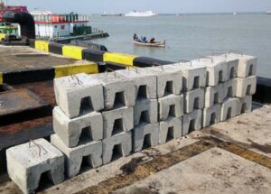
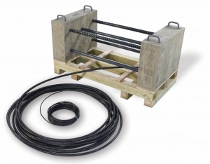
MATCOR marine sled anodes (Sea-Bottom™ Anodes) are designed with the cable connections routed inside a high density polyethylene (HDPE) protective pipe with holes to provide a level of mechanical protection. Then we use concrete weights to help secure the HDPE pipe (with the cable inside) to the sea bottom so that they are not subject to wave or tidal action.
The protective housing is pictured here and called out as item 4 on the drawing on page 3 of our Sea-Bottom Marine Anode Sled brochure. For the concrete weights, you can use a variety of methods from sacks of concrete to custom formed concrete cast weights. Below is a photo of the weights that were locally supplied to us for a recent project in Indonesia. These weights are installed by divers during the sled anode installation.
For assistance with impressed current anode system design, MATCOR’s Sea-Bottom Marine Anode Sleds, project management or installation, please contact us at the link below.
One of the key decisions for any cathodic protection system design is the choice between an impressed current anode system or a galvanic (or sacrificial) anode system. This is especially true for marine applications where cathodic protection is commonly applied to structures such as steel piling systems on jetties and piers for corrosion protection. A recent MATCOR project highlights the choice between ICCP and Galvanic systems on a newly constructed jetty in Surabaya, Indonesia.
Impressed Current Anode Systems vs Galvanic Anode Systems
Click on the image above to read the full case study comparing impressed current cathodic protection utilizing marine anode sleds with a galvanic anode system.
This case study article, which appeared in the October issue of Materials Performance includes a comparison of key factors for commonly used galvanic (aluminum) anodes and impressed current (titanium with mixed metal oxide) anodes. The key differences between an impressed current anode system and a galvanic anode systems include:
Anode consumption rates
Current density (CD) limits
Driving voltage
Anode quantities
Installation time and costs
The article describes these key differences in more detail.
Conceptual Design – Galvanic vs Impressed Current
Jetty applications can be designed using either galvanic anodes or impressed current anodes, and often it is a matter of client or designer preference. For this project in Indonesia, the cathodic protection designer reviewed both system types to determine the ideal design for this application based on a 30-year anode life. The final decision was based on several factors including total number of anodes and installation time required, in addition to safety considerations.
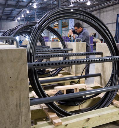
Impressed Current Anode System Installation and Commissioning
The final design called for the installation of six marine anode sleds, which took less than a week to complete.
For more details about this impressed current anode system solution for jetty piling cathodic protection, please read the full article in the October issue of Materials Performance. You can also access the full article HERE.
For assistance with impressed current anode system design, MATCOR’s Sea-Bottom Marine Anode Sleds, project management or installation, please contact us at the link below.

 MATCOR can help.
 At MATCOR, we pride ourselves on being a world class manufacturer of unique
 An engineer’s favorite answer to any question is “It depends” and this is certainly the case with HDD installations. The important thing to note is that when attempting to pull a linear anode through a bore hole, there is a chance that the pulling forces on the anode will exceed the strength of the anode and cause the anode to break. Even if the anode does not break completely, stretching of the anode can weaken or damage the internal header cable or anode to cable connections.
 The protective housing is pictured here and called out as item 4 on the drawing on page 3 of our