A linear anode system may be an economical alternative to applying a new pipeline coating system or replacing aging pipelines.
by Ted Huck
Introduction: Addressing Aging Pipelines and Pipeline Coatings
 External corrosion is one of the significant threats facing pipeline operators worldwide. Historically, pipeline owners have employed a two-tiered approach towards mitigating corrosion risks. The primary defense against corrosion has been to apply a pipeline coating system that acts as a barrier, protecting the steel pipe from its environment. Cathodic protection is employed to supplement the coating system by providing protective current to the holidays or defects within the coating system. As with any aging structure, however, time takes its toll – for older pipelines this often results in an older coating system that starts to degrade in its primary function of protecting the pipeline from its environment.
This paper addresses the fundamental issue that many operators will face when evaluating their aging pipelines and pipeline coating systems. That issue is, quite simply, what is the best strategy to remediate an aging pipeline with deteriorating coating systems to maintain compliance with international standards for pipeline integrity. The options are to improve/upgrade the cathodic protection system, recoat the pipeline, or replace the pipeline. Each of these options will be discussed in detail and a decision matrix will be provided to facilitate the operator’s decision-making process.
Pipeline Coating Systems
Coating systems have been used on buried pipelines during the last hundred years and the technology continues to be the subject of significant research and innovation. Pipeline coating manufacturers are continually searching for better coatings to meet the varied needs of industry. Initially, the coatings were simple mixtures of crude pitches and solvents. These early bitumastic/asphaltic systems evolved into engineered coal tar enamel coating systems, which were prevalent into the 1960’s. The introduction of fusion-bonded epoxies (FBE) in the 1970’s quickly captured much of the pipeline market, although polyethylene, polypropylene and coal tar enamels are still used as well. The coatings industry continues to research and develop improved methods of providing more reliable and more economical coating systems.
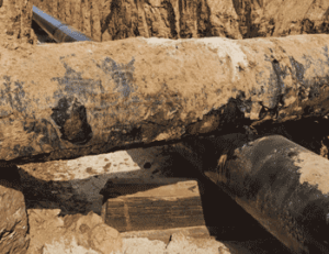
When evaluating aging pipelines, coating condition is one of the critical issues that must be addressed. The coating provides the primary defense against pipeline corrosion and as the coating system ages and deteriorates, then the risks of corrosion increase exponentially. One of the challenges that must be addressed by pipeline owners is properly identifying the type and vintage of the coatings along a given pipeline. In many cases, different sections of pipeline may have different coating systems depending on the age of the pipeline and the standards in place at the time a section of pipe was installed.
Another critical consideration when evaluating aging pipeline coating systems is to identify whether the coating system fails shielding or non-shielding. Coating systems that fail in a non-shielding mode do not inhibit the flow of current making cathodic protection a viable alternative when considering how to remediate these lines. Other coating systems, principally tape coating systems, can fail in a manner that shields cathodic protection current and thus greatly reducing the possible remediation methods available.
Modern, over-the-line survey technologies have proven to be quite effective in evaluating coating quality and finding coating holidays. Technologies such as pipeline current mapping (PCM) which utilize a carrier signal transmitted along the pipeline with a receiver measuring the line attenuation along the pipeline length can accurately pinpoint areas of significant coating degradation even under concrete or asphalt. The information gathered using PCM in conjunction with pipe to soil close interval surveys (CIS) and direct current voltage gradient (DCVG) testing form the basis for identifying critical risk areas along aging pipelines. In-line inspection technologies using smart pigs also provide valuable data regarding coating quality.
Cathodic Protection
Pipeline coating systems are typically augmented by the application of cathodic protection. With a well-coated pipeline, cathodic protection can be economically applied to protect the coating holidays and defects by placing discreet anode beds that distribute current over long distances. In many cases ground beds can be located several kilometers apart and still provide sufficient current distribution to protect the entire pipeline. With some of today’s high technology factory applied coatings, the coating efficiencies are exceptionally high and the groundbed output requirements are very low. These discreet ground bed systems can either be deep anode ground beds or shallow ground beds located some distance off the pipeline.
Several issues must be considered when designing a cathodic protection system. These include coating quality, soil resistivity, available locations for electrical power, ground bed right of way issues, accessibility for maintenance, AC and DC stray current interference, and a host of additional issues. What is critical for aging pipelines is the regular evaluation of the effectiveness of the CP system. Frequently, as pipelines age and the coating quality begins to deteriorate, the CP systems are unable to provide sufficient current properly distributed to meet established cathodic protection criteria. In many cases, simply ramping up the output of the existing system or adding additional ground beds does not prove sufficient to address the problem.
Learn about soil resistivity testing.
Aging Pipeline Systems
Problem Identification
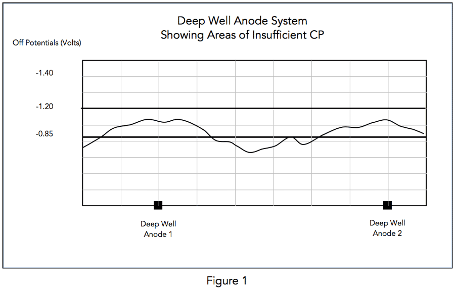
Aging pipeline systems with deteriorating coating systems suffer from poor current distribution and are characterized by areas of low potentials and exceedingly high levels of applied current density. The challenge with these pipeline systems is controlling current distribution to achieve the prescribed polarization levels consistent with international standards for adequate cathodic protection.
Figure 1 shows a deep well anode system with current output such that some areas are not meeting required off-potentials of -0.85 Volts to meet NACE criteria.
Initial Responses
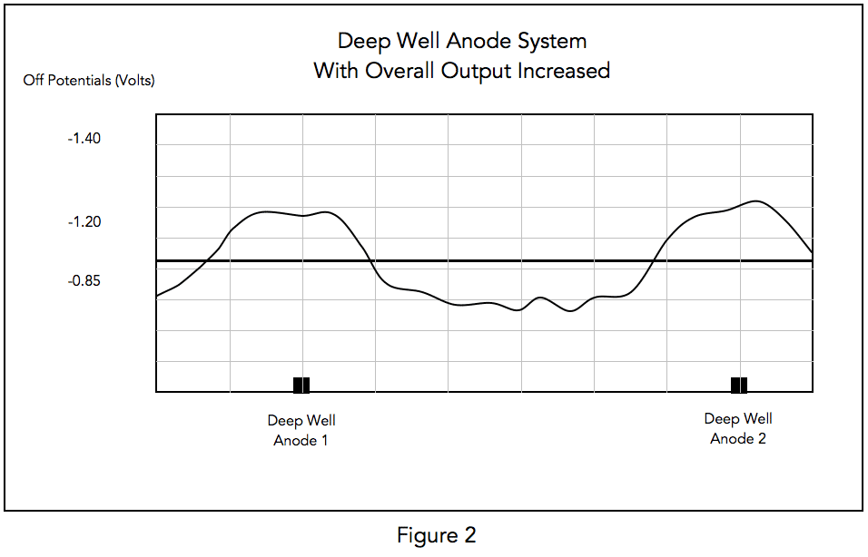
The typical response to this problem is to increase the overall output of the deep well system (see Figure 2.) This generally does not alleviate the problems of not meeting the off-potential criteria and leads to over-polarizing the piping (potentials greater than -1.2 Volts.) This can result in coating disbondment further exacerbating the problem. The higher output current increases the ground bed’s consumption rate reducing operating life while raising operating costs appreciably. All this occurs without achieving the required levels of polarization to meet cathodic protection criteria.
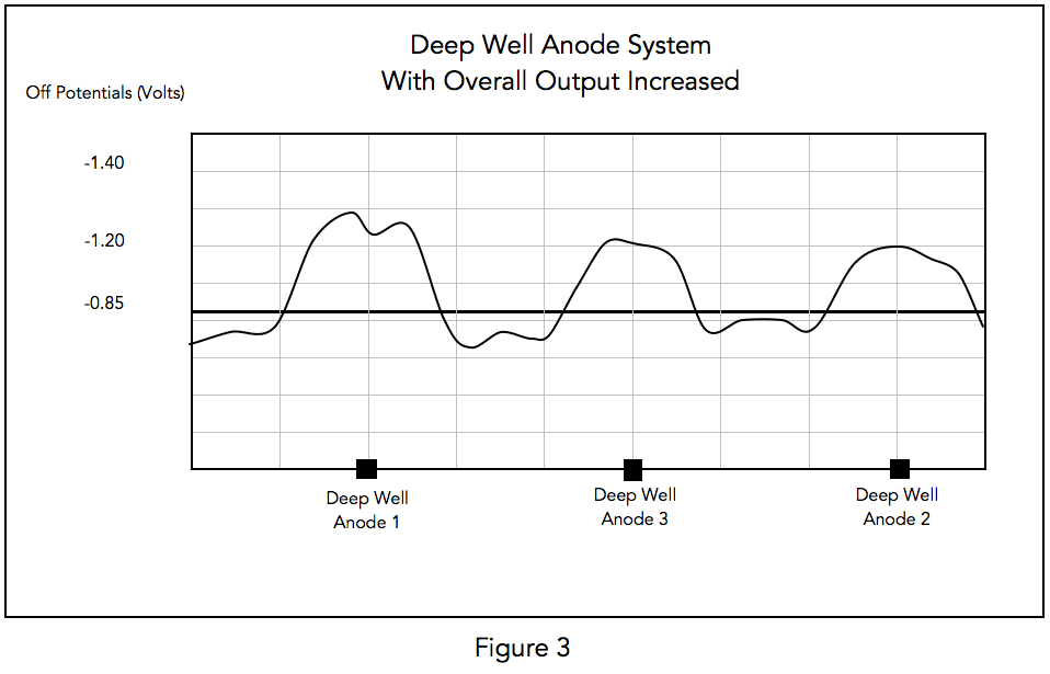
The next step that is taken to fix the cathodic protection current distribution problem is to add additional ground beds to reduce the distance between point sources. This too, proves to be an ineffective solution as the new ground bed provides only limited additional benefit (see Figure 3.)
Remediation Options
The problem cannot be economically resolved by the addition of an ever-increasing number of ground beds applying greater and greater amounts of additional current. The pipeline operator is then faced with a limited number of options: recoat the pipeline, replace the pipeline, or install a linear anode cathodic protection system.
Recoating/replacing is the only viable alternative for pipeline systems utilizing shielding type coatings such as tape wrap systems. Recoating costs typically run several hundred dollars per foot in open right of way areas and can be significantly more expensive in congested urban locations (these are ballpark numbers applicable to the United States and can vary significantly.) Recoating, when properly performed, can restore the pipeline coating system to an as new condition greatly extending the service life of the recoated section. The critical issue is to assure that the recoating is executed by an experienced coatings contractor with rigorous quality controls in place. Pipeline replacement is expensive and only performed when extensive third-party damage, significant corrosion or other extenuating circumstances warrant.
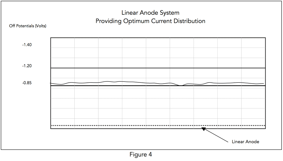
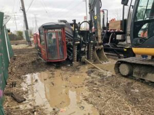
An economically attractive alternative to recoat/replace options is to utilize a linear anode configuration in lieu of point anode systems. This option is only viable when the coating system is non-shielding – this would include asphaltic and epoxy type coating systems. The application of a linear anode system typically costs between $20-30/foot in open right of way (again these are general price guidelines and can vary significantly.) In suburban or urban areas, horizontal directional drilling (HDD) can be an effective installation method with minimal surface disruptions. These linear anode systems eliminate the distribution problems experienced by point anode systems; they are in effect an infinite series of point anodes, which provide an optimum current distribution (see Figure 4.)
In addition to confirming that the pipeline coating system is non-shielding and appropriate for the application of linear anodes, the linear anode system design must take into consideration the critical issue of voltage drop and its affect on current attenuation. Voltage drop can have a significant impact on DC power distribution to the linear anode system. Ideally, rectifiers would be located no further than half a mile to a mile apart, however, practical considerations including availability of AC power, right of way issues and other factors can force this to be extended further complicating the system design and affecting the installed cost.
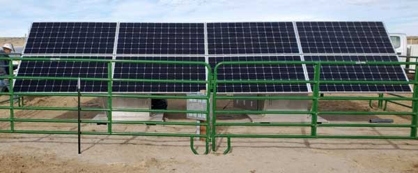
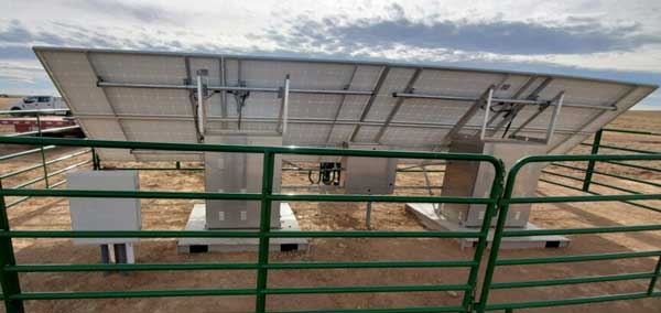
While the design can be complicated by voltage drop considerations, one of the benefits of a linear anode system is that the power consumption is relatively low. Ground bed resistance, as determined by Dwight’s Equation, is significantly affected by anode length and this results in very low groundbed resistance values for linear anode systems relative to conventional ground beds. This makes the linear anode system much more suitable for low wattage power sources such as solar arrays and thermo-electric generators (TEG’s) than conventional ground beds whose wattage could be two or more times that of a linear anode system to achieve the same current discharge.
Conclusion
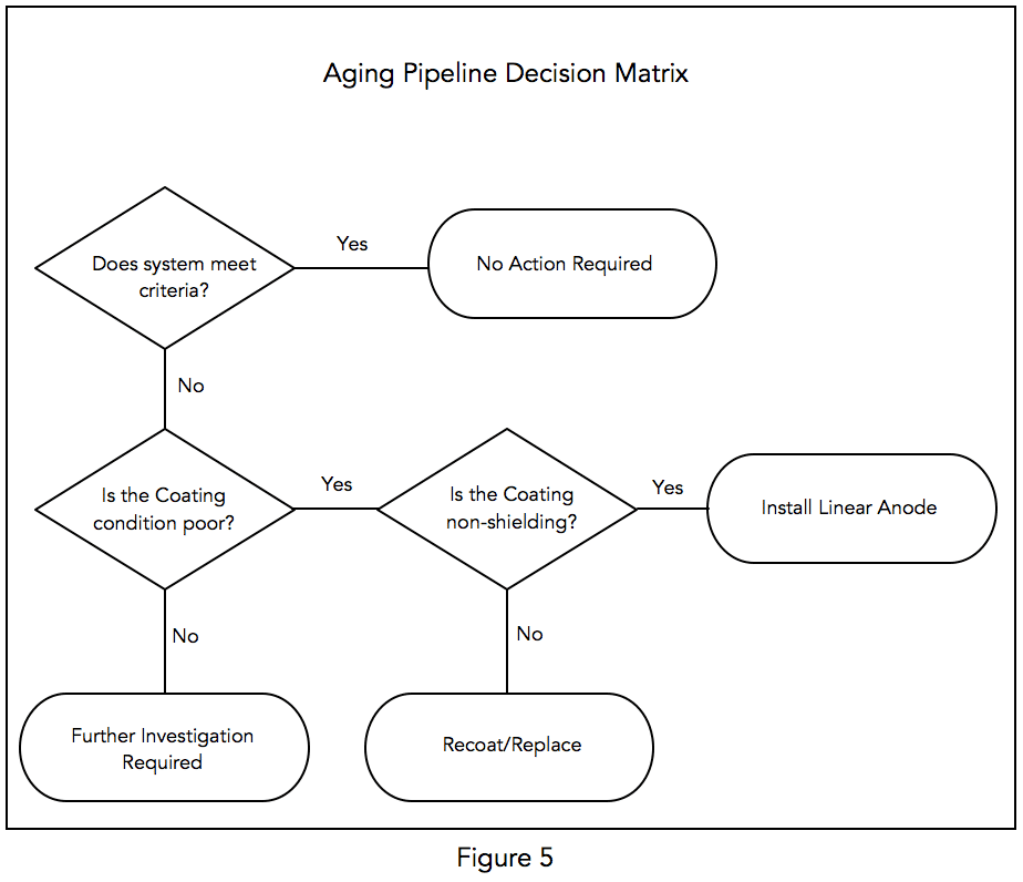
Aging pipeline systems with deteriorating coating systems present a difficult challenge to pipeline operators. The more the coating deteriorates, the more difficult it is to distribute current further away from the ground bed. The natural response to ramp up the ground bed output does an inadequate job of throwing current further but does result in increased current flow, higher current densities and over polarization near the ground bed further stressing the coating system. Adding additional ground beds also allows more current to be applied to the pipeline, but does not alleviate the current distribution issues. Ultimately, pipeline operators are faced with the choice of recoating/replacing the pipeline, or installing a linear anode system. The flowchart below (Figure 5) provides a decision matrix. Note that aging pipeline systems whose coating systems are determined to be in good condition through indirect and direct examination, require additional investigation to determine why criteria is not being achieved.
For assistance with evaluating aging pipelines or installing linear anode cathodic protection systems, please CONTACT US.
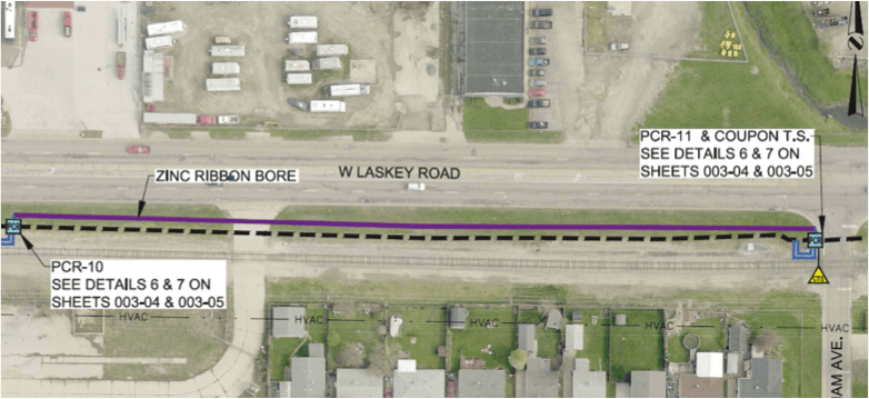
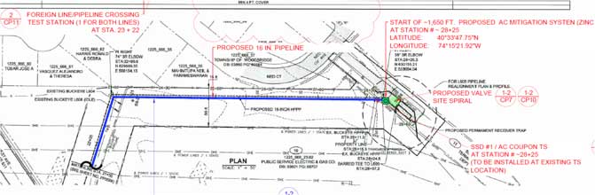 This case study highlights some of the challenges associated with choosing AC mitigation design criterion for a new pipeline construction project. The specific project consisted of approximately 200 miles of pipeline with another 35 miles of lateral lines and included compressor stations, metering valves and a valve station. The final approved right of way consisted of 41 identified transmission lines spanning 5 different utility owners. MATCOR’s scope of work included designing both the CP system and modeling and designing an AC Mitigation system to address the extensive HVAC colocations.
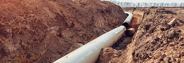
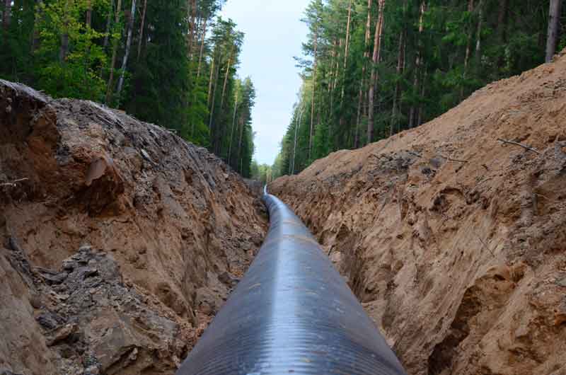
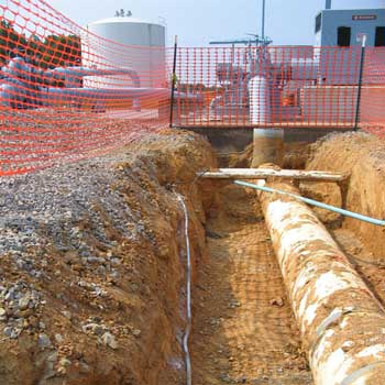 Installation in the same trench as the buried piping during initial construction greatly reduces installation costs


