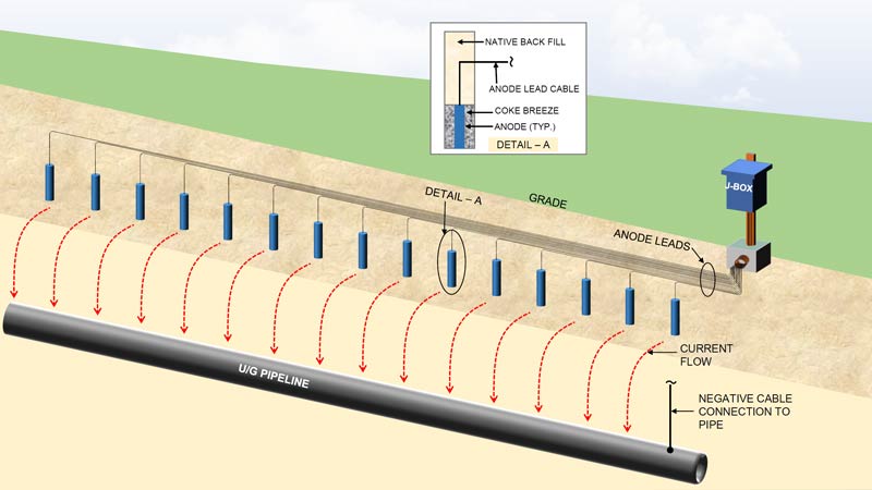
A common cathodic protection system approach is the use of a shallow horizontal anode bed. These are typically defined as an anode system consisting of a series of multiple individual anodes installed either vertically or horizontally at a depth of less than 15m (50ft) and connected to a single power source. These are particularly effective in areas where drilling deep anode beds is not feasible or practical.
The typical anode used in shallow anode bed applications is an impressed current anode. These can be high silicon cast iron, graphite anodes or mixed metal oxide tubular anodes. The anodes may be pre-packaged in a canister filled with coke backfill, or they can be installed in a vertically drilled/augured hole or a continuous horizontal trench with backfill installed around the bare anode. The anodes can be installed in parallel to a common header cable or can have individual leads all routed to a cathodic protection junction box and connected in parallel inside the junction box.
Shallow Horizontal Anode Bed with Individual Anodes
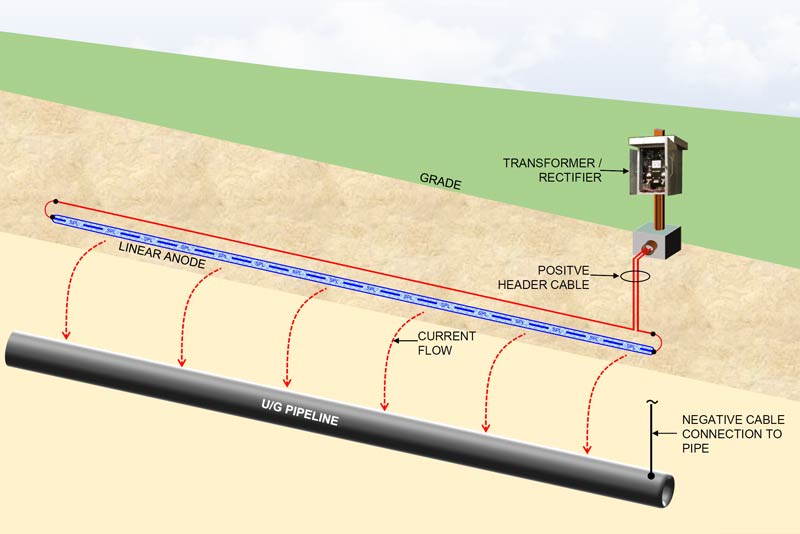
A New Approach: Continuous Linear Anodes
Another approach that is gaining acceptance in the corrosion industry is the use of a single continuous linear anode as an alternative to multiple individual discreet anodes that are field connected to form an anode bed. There are several advantages to using a single continuous linear anode to create a shallow horizontal anode bed:
Shallow Horizontal Anode Bed with a Single Linear Anode
Advantages of linear anodes for shallow horizontal anode beds
Ease of installation The use of a single continuous linear anode assembly can significantly reduce installation time by eliminating numerous field splice connections of multiple individual anodes to a header cable.
Reliability The entire linear anode assembly is factory manufactured and tested with internal factory connections that are more reliable than a field connection. The assembly is designed with an internal header cable for redundancy and can be manufactured with an integral external return header cable, eliminating all field splicing and connections.
HDD Installation The use of a linear anode for shallow anode bed design allows for the use of HDD (horizontal directional drilling) to install the continuous anode assembly. This can significantly minimize the installation footprint and greatly reduce installation time and costs. This also allows for a deeper installation to facilitate locations where surface activities such as deep tilling farming operations might preclude a shallower anode system installation.
Cost Effectiveness The use of linear anodes can be extremely cost effective, resulting in a much lower cost installation. This is especially true when considering the overall cost per amp year given the longer design life of mixed metal oxide based linear anode systems.
MATCOR has extensive experience designing and installing shallow horizontal anode beds, including the use of our HDD installation crews and state-of-the-art equipment to minimize surface impact in sensitive areas.
Contact us at the link below to find out if a linear anode cathodic protection system is right for your application.
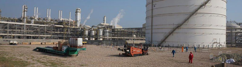
Last month, MATCOR successfully completed the first ever HDD tank cathodic protection system installation in the Middle East, utilizing a replaceable anode system.
Background—Initial Recommendation for HDD Cathodic Protection System
Equate Petrochemicals is one of the world’s largest producers of Ethylene Glycol. They initially contacted MATCOR in 2012 to discuss options for cathodic protection on a critical service Ethylene storage tank at their flagship Kuwait petrochemical facility. This tank was originally constructed in 1995, and the initial CP system installed with the tank was no longer providing sufficient current to achieve NACE Criteria. At the time, MATCOR suggested installing anodes directly under the tank using horizontal directional drilling technology. The plant’s engineering and operations team had significant reservations about this approach. The tank was critical to the plant’s operation and could not be taken out of service. Should the HDD operations result in damage to the structural integrity of the tank, the results would be catastrophic.
Perimeter Anodes—An (Unsuccessful) Alternative Approach
As a result of Equate’s concerns in 2012, they attempted an alternate approach, suggested by others, using perimeter anodes. Discreet anodes were installed offset around the perimeter of the tank—thus avoiding any possible risk to the tank during the anode installation. The use of perimeter anodes around larger diameter tanks is generally not a good idea. This is because it is very difficult to drive current to the center area of the tank, often resulting in adequate protection levels only for the outer edges of the tank bottom. For the Ethylene Storage Tank, the presence of heating pipes below the tank bottom only exacerbated the current distribution challenges. Ultimately, the results were not satisfactory.
In 2018, the plant engineering team reached back out to MATCOR to discuss our HDD solutions.
Replaceable Anode System Solution
MATCOR provided the plant with a detailed proposal to design and install a complete cathodic protection system using MATCOR’s Replaceable Tank Anode system. The RTA system is based on installing MATCOR SPL linear anode assemblies in a series of parallel slotted PVC pipes that have coke backfill pneumatically blown into the PVC pipe as part of the anode system installation. In addition to the linear anode segments and coke backfill, the slotted PVC pipes have a venting system to allow gases produced during the cathodic protection reaction to vent. This prevents gas buildup and blockage inside the PVC anode pipe.
One of the key advantages of the RTA system is that once the PVC tubes are installed, it is possible to flush out the anode assemblies and coke backfill should the anode assemblies fail and/or they are at the end of their design life making this a replaceable anode system that will assure cathodic protection for the entire service life of the tank.
Additionally, a slotted Reference Cell Tube would be installed to allow for two calibrated fixed cathodic protection reference electrodes to be inserted for full polarized and non-polarized potential measurements across the entire tank bottom. This would allow for testing of the CP system with calibrated reference electrodes for the life of the tank.
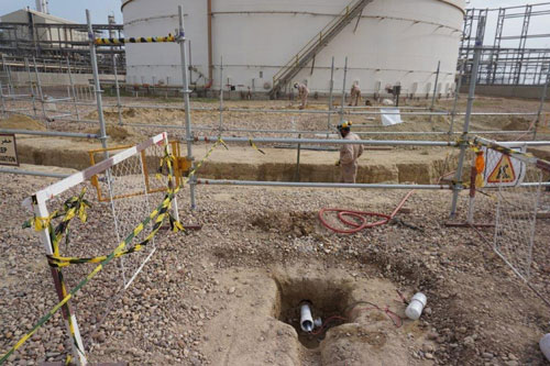
Experienced HDD Installation—Assuring a Safe Installation
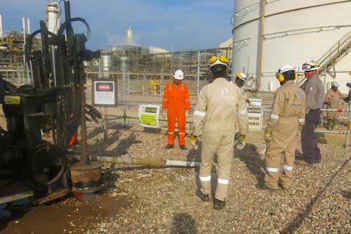
While the plant conceptually agreed with MATCOR’s solution from a technical perspective, there remained a significant concern within the plant’s operation and safety groups about drilling under this critical service tank and the possibility of a catastrophic event should the drill head drift up to the tank bottom. MATCOR put together a thorough installation procedure including detailed information on the sophisticated drill head tracking systems being utilized to assure that the drill head location was being continuously monitored throughout the bore. Utilizing an experienced local HDD drilling sub-contractor, MATCOR deputed its senior HDD installation drilling supervisor to Kuwait for the installation. Our Senior HDD Drilling Supervisor has completed hundreds of tank HDD installations in the United States and his on-site presence, along with the advanced electronic tracking package being used, assured that each bore went as planned.
Replaceable Anode System Installation Complete!
In December of 2019, MATCOR, working with our local Kuwaiti sub-contractor and the client’s engineering, construction and safety teams, successfully completed the installation of the replaceable anode system. The initial commissioning results showed that the anodes were installed properly. Each anode was distributing current as expected, and the polarization levels were meeting appropriate NACE criteria. The system has been left to operate and fully polarize. A subsequent visit by MATCOR’s technical team is scheduled in early 2020 to make final adjustments to the anode system current output and to confirm that the system continues to meet NACE criteria.
Conclusion
MATCOR’s successful installation in Kuwait of a horizontal directional bored CP system under an existing critical service tank is a first for the Middle East Region. The innovative MATCOR design, combined with the technical knowledge and operational expertise, makes this an interesting and viable option for other tank owner/operators worldwide to consider for their existing tanks with CP systems that are not performing properly.
To get in touch with our team of cathodic protection and AC mitigation experts for more information, to ask a question or get a quote, please click below. We will respond by phone or email within 24 hours. For immediate assistance, please call +1-215-348-2974.
This guide explores how Vapor Corrosion Inhibitors (VCIs) work, their diverse applications, and why they’re becoming a cornerstone of modern corrosion prevention strategies. Whether you’re in oil and gas, manufacturing, or aerospace, discover how VCIs can transform your approach to corrosion management.
Corrosion poses a significant threat to infrastructure and equipment across industries, from pipelines to storage tanks. VCIs offer a solution, using advanced chemical technology to protect metal surfaces and prevent costly damage.
As a leader in the above-ground storage tank corrosion control industry, MATCOR has partnered with Zerust® Oil & Gas to provide innovative VCI solutions for customers seeking advanced corrosion mitigation strategies.
What are Vapor Corrosion Inhibitors?
Vapor Corrosion Inhibitors (VCIs) are advanced chemical compounds that prevent corrosion by diffusing through confined spaces and bonding with metal surfaces. This process creates an invisible yet highly effective barrier that blocks water, oxygen, and other contaminants from initiating degradation.
Key features:
Create a passive oxide layer that inhibits chemical reactions
Can be applied in various forms, including powders, liquids, or impregnated materials.
Long-lasting protection for months or years, depending on conditions.
Why Choose VCIs?
Vapor Corrosion Inhibitors (VCIs) stand out among corrosion prevention solutions due to their ease of application, flexibility, and proven effectiveness. Compared to other methods like wax, VCIs offer several key advantages:
Ease of Installation: VCIs are easy to apply, requiring no heating—just simple mixing with potable water and injection through vent pipes, ensuring efficient distribution.
Broad Compatibility: VCIs work seamlessly with other corrosion prevention methods, such as coatings and cathodic protection, enhancing overall protection strategies.
Cost-Effectiveness: By extending the lifespan of assets and reducing the need for frequent maintenance, VCIs provide a high return on investment over time.
Allows Monitoring: VCI effectiveness can be monitored in real time using coupons, ER probes, or UT probes, with the option for remote monitoring units (RMUs). In contrast, wax requires in-line inspection (ILI) runs for evaluation.
Non-Invasive: Unlike some traditional methods, VCIs do not require disassembly for application, making them a convenient choice for hard-to-reach areas.
Versatile Applications: VCIs are available in various forms, including films, papers, powders, liquids, and emitters, making them adaptable to a wide range of industrial needs.
Removability: VCIs can be easily washed out and removed if necessary, offering flexibility for future maintenance or operational adjustments.
Environmentally-Friendly: VCIs are an environmentally friendly solution for corrosion prevention, offering biodegradable formulations, non-toxic options for sensitive industries, and contributing to sustainability by reducing waste and extending asset life.
Through our partnership with Zerust® Oil & Gas, MATCOR delivers these benefits with proven products backed by extensive research and industry expertise.
Applications of Vapor Corrosion Inhibitors Across Industries
Oil and Gas: Protects internal surfaces of pipelines after hydrotesting and safeguards tanks bottoms from localized corrosion. Learn more about pipeline corrosion risks and prevention methods in our Pipeline Corrosion and Prevention—A Comprehensive Guide.
Manufacturing and Industrial Equipment: Shields components during storage, shipping, or idle periods.
Marine and Offshore: Mitigates corrosion from saltwater and high-humidity environments.
Aerospace and Automotive: Protects critical systems like engines and fuel tanks during long-term storage.
Infrastructure and Utilities: Prevents corrosion in water pipelines, bridges, and utility equipment.
Monitoring and Maintenance
To ensure the long-term effectiveness of VCIs, regular monitoring is essential. Techniques include:
Coupons: Small metal pieces placed in the protected environment to assess corrosion rates.
ER Probes: Monitor changes in electrical resistance to track corrosion over time.
Replenishment: Determined based on environmental conditions and the observed depletion rate of VCIs. Factors influencing replenishment frequency include:
The rate of leakage through the tank chime.
Operating temperature and environmental conditions.
Properties of the substrate, such as sand or concrete.
The initial amount of VCI chemical applied.
Typically, VCIs provide effective protection for 3–5 years, though some applications may last longer under optimal conditions. Proper monitoring ensures VCIs maintain consistent protection and helps operators identify the appropriate timing for replenishment to sustain corrosion prevention.
VCIs and Industry Standards
Vapor Corrosion Inhibitors (VCIs) are gaining recognition in industry standards as a flexible and effective corrosion prevention tool. While they are often used to complement cathodic protection (CP), they are also being acknowledged as standalone solutions in scenarios where CP may not be feasible.
API 651 and API 2610: Standards such as API 651 include VCIs as an alternative for situations where CP systems are unsuitable, and API 2610 outlines their use under tank bottoms.
Regulatory Adoption: Organizations like PHMSA and the State of Florida have endorsed VCIs for their versatility, particularly in cases where CP systems are not functional or economical.
These endorsements highlight the growing recognition of VCIs as a versatile tool for corrosion prevention, whether as a standalone solution or a complement to existing systems like CP.
The effectiveness of Vapor Corrosion Inhibitors (VCIs) is well-supported by independent research, including a comprehensive 2018 study published by PRCI (Pipeline Research Council International). This study offers critical insights into the capabilities and limitations of VCIs:
Effectiveness in Corrosive Environments: VCIs were found to effectively mitigate pitting corrosion in steel exposed to corrosive sand. However, the study noted that VCIs are not as effective as cathodic protection (CP) for reducing pitting corrosion in certain conditions.
Importance of Proper Application: The study emphasized the need for following manufacturer-recommended concentrations, as inadequate levels of VCIs were shown to be ineffective.
Monitoring Compatibility: ER probes can be used to monitor the efficacy of VCIs, providing valuable data on corrosion rates and the need for replenishment.
Compatibility with Cathodic Protection: VCIs are compatible with impressed current cathodic protection systems. However, they can alter the native potential of steel, which must be considered when selecting CP criteria in accordance with NACE SP0193.
Vapor Corrosion Inhibitor Case Studies: Real-World Success with VCIs
Pipeline Preservation with VCI in West Texas
MATCOR and Zerust® collaborated on a pipeline preservation project in West Texas, injecting over 24,000 gallons of VCI solution into pipeline manifolds. This approach provided effective corrosion protection during construction and harsh environmental conditions.
MATCOR conducted a casing repair for a high-pressure natural gas line that had settled, losing contact with its protective casing. The solution included sealing the casing and injecting VCIs through the vent pipe, providing effective corrosion protection without excavation.
Q&A: Common Questions About Vapor Corrosion Inhibitors (VCIs)
Are VCIs a permanent solution?
No, VCIs have a finite lifespan. Their effectiveness typically lasts 3-5 years, depending on factors like environmental conditions, application methods, and leakage rates. Regular replenishment is needed to maintain protection, with some applications lasting up to 15 years under ideal conditions.
How are VCIs applied to above-ground storage tanks?
VCIs can be applied as powders or liquids, depending on the tank type (new,in-service, or under inspection). The method varies based on substrate material (ie. sand or concrete), but long-term replenishment planning is essential to sustain protection.
Can VCIs replace other corrosion prevention methods?
VCIs are not typically used as a standalone replacement for other methods but are effective for short-term corrosion protection or in scenarios where other solutions are not practical.
Can VCIs enhance other corrosion prevention methods??
Yes, VCIs work well alongside existing methods by addressing localized corrosion in hard-to-reach areas like gaps, crevices, and irregular surfaces. This complementary approach strengthens overall protection.
How is VCI performance monitored?
VCI effectiveness is monitored using coupons, ER probes or UT probes. These tools measure corrosion rates and help identify when replenishment is required. While ER probes track average corrosion rates, they can also infer localized risks like pitting.
What standards and regulations support VCI use?
VCIs are recognized by standards such as API 651 and API 2610 for specific applications, and they are included in the upcoming NACE TG543 guidelines. Regulatory bodies like PHMSA also acknowledges VCIs as a valid corrosion prevention tool, especially when other methods are infeasible.
Conclusion: The Future of Corrosion Prevention with VCIs
Vapor Corrosion Inhibitors (VCIs) are transforming the landscape of corrosion prevention across industries. From pipelines and storage ranks to marine and aerospace applications, VCIs provide a versatile, cost-effective, and environmentally friendly solution for protecting metal assets. Their ability to adapt to various environments and integrate with other corrosion prevention methods makes them a critical tool for modern infrastructure and equipment management.
Through our partnership with Zerust® Oil & Gas, MATCOR delivers proven VCI solutions backed by extensive research and industry recognition. Whether you’re seeking to enhance existing systems or explore standalone VCI applications, our team is ready to help you develop a customized strategy to protect your assets and reduce long-term maintenance costs.
To get in touch with our team of corrosion experts for more information, to ask a question or get a quote, please click below. We will respond by phone or email within 24 hours. For immediate assistance, please call +1-215-348-2974.
This is the time of year when thoughts turn to Thanksgiving and Christmas vacations, using up all your remaining vacation and wondering what to do with any leftover 2019 cathodic protection budget monies. More than likely, it is too late to schedule and complete new projects. MATCOR along with most of our competitors have full construction schedules and adding additional commitments is quite difficult.
Click HERE to get in touch with your MATCOR account manager for more information, to ask a question or get a quote. Or, complete our contact form at the link below and we will respond by phone or email within 24 hours. For immediate assistance, please call +1-215-348-2974.
Evan Savant, EnLink Midstream reached out to the MATCOR Technical Team asking about AST cathodic protection system tank isolation:
“Can you advise on the importance of isolation for a new AST connected to a Pipeline, and can you advise on the need to isolate the tank cathodic protection from the tank grounding?
MATCOR’s Director of Engineering, Kevin Groll PE, NACE CP4 responded:
I am unaware of any papers or technical documents on the subject, but I will summarize as follows:
Why can a lack of isolation hurt your cathodic protection? When trying to protect any type of structure from corrosion, cathodic current loss to nearby structures is always a concern. Losses can occur when the structure in question is directly bonded to other structures which may “steal” current. Offending metal structures that are close to the cathodic protection anode and structures with better resistance to earth (e.g., bare copper grounding, bare driven piles, etc.) will more likely take a significant amount of current.
How do you obtain isolation without losing overvoltage protection?
To prevent current loss, your target structure must be electrically isolated from the offending structures. However, once you isolate a structure, you will lose grounding (if it was purposefully grounded) and you will lose protection against overvoltage events, AC faults, and lightning strikes. Therefore, to obtain DC isolation but maintain AC continuity and overvoltage continuity, we use solid state decouplers (SSDs) and polarization cell replacements (PCRs). The primary difference between these devices is how much surge current they will carry.
Tank cathodic protection design considerations.
When we design an under-tank CP system with concentric rings, we assume that we will not have isolation from grounding and facility piping, and we also assume that most of the current will get to the tank bottom because of the proximity of the anodes. This is not always the case, as we saw in a recent project, but for the most part concentric ring systems can be powered high enough to overcome the lack of isolation.
Horizontal directional drilling installed linear systems show approximately 1.5 to 2 times as much current is required as a concentric ring system due to current losses. Again, we usually factor in enough current capacity to overcome these losses.
Deep anode systems and semi-deep anode systems suffer the worst losses. These systems will sometimes require isolation of the tanks to prevent critical current loss. If a system is already in place, testing can be performed to determine how much loss there is to existing structures by measuring the current returned on ground rods and pipes. This is accomplished by using clamp-on current meters around wires/rods and Swain meters around pipes.
It is important to note that tank terminal isolation and grounding are factors in these complex tank terminal applications that must be considered in the proper design of Cathodic Protection. MATCOR’s experienced team of engineers can evaluate your specific application and make the appropriate recommendations.
To get in touch with our team of cathodic protection experts for more information, to ask a question or get a quote, please click below. We will respond by phone or email within 24 hours. For immediate assistance, please call +1-215-348-2974.
This article describes the components of a cathodic protection rectifier, and when to use oil cooled cathodic protection transformer rectifiers vs. air cooled rectifiers.
When it comes to cathodic protection power supplies, conventional transformer rectifier circuits have long been employed by the cathodic protection industry for impressed current CP systems. These power supplies (commonly referred to as rectifiers in the CP world) consist of three main components; the transformer, the rectification stack, and a cabinet to house these components. The transformer takes the input AC voltage on the primary side and controls the output AC voltage on the secondary side. The rectification stack, typically silicon diode stacks which have largely replaced older less efficient selenium stacks, convert the AC input wave form into a DC wave form by cycling the AC flows in one direction and blocking in the other. Additional components typically include circuit breakers, fuses, voltage and current output meters, lightning arrestors, surge suppressors, transformer tap bars, and monitoring systems.
Typical Air-cooled Rectifier
The majority of these Rectifiers are housed in air-cooled NEMA 3R enclosures – these enclosures are typically constructed of hot dipped galvanized steel, aluminum, stainless steel or painted steel. NEMA 3R enclosures are intended for outdoor use. They provide a degree of protection against falling rain and ice formation but are not completely water tight or weather proof and could be subjected to beating rain or streams of water, under certain conditions, entering the enclosure. This is the most common type of rectifier enclosure in the industry.
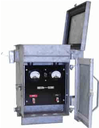
When and Where to Use Oil Cooled Cathodic Protection Transformer Rectifiers
Oil Cooled Rectifier
For some applications; however, the use of air cooled NEMA 3R enclosures is not recommended or not suitable. The three most common reasons not to use air-cooled NEMA 3R enclosures are:
Rectifier transformer size is too large to support an air cooled enclosure. For a small percentage of impressed current CP systems where the power requirements (measured in DC Watts) are sufficiently high that the cooling capacity of the enclosure is insufficient for the heat generated by the transformer (typically anything more than 12kW for single phase and 18kW for three phase.)
Severe environment locations where high humidity, dust or other situations could shorten the life of a standard air cooled rectifier. Marine and near shore applications often fall into this category.
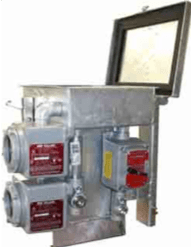
The enclosure must be in a hazardous classified location requiring Class 1 Div. 2, Group D compliant enclosure – commonly referred to as Explosion Proof.
Oil Cooled Rectifier for Hazardous Locations
For these applications, oil cooled cathodic protection transformer rectifiers are typically specified. As implied in the name, the oil cooled rectifier utilizes an enclosure that has a sealed reservoir which houses the transformer and transformer tap bars and is filled with a special transformer oil. The transformer oil provides better heat transfer and dissipation and the larger case facilitates improved heat removal.
It is very important to note that standard oil cooled rectifiers are NOT explosion proof. For an oil cooled rectifier to be considered Explosion Proof, the components that are not immersed in the transformer oil reservoir must be housed in special Explosion Proof fixtures. Simply specifying oil cooled when ordering a rectifier does not satisfy the requirements for locating the rectifier in a hazardous Class 1 Div.2 location without also including the additional provisions required for the explosion proof fittings.
To get in touch with our team of cathodic protection experts for more information, to ask a question or get a quote for cathodic protection materials or related construction services, please click below. We will respond by phone or email within 24 hours. For immediate assistance, please call +1-215-348-2974.
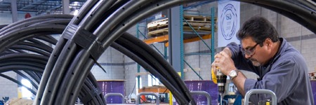
MATCOR is pleased to announce that we are now capable of performing Helium leak testing on our full range of linear anode products as an optional testing service. This is a common practice among companies and product developers that provide products that could potentially leak gas or that require water tightness. Products commonly leak tested include refrigeration lines, vehicle brake lines, and devices that contain potentially harmful or deadly substances. Helium is the second smallest element (Hydrogen is the smallest), which means that it is valuable for leak testing. Smaller molecules naturally can find smaller gaps or defects from which to leak. Unlike hydrogen, however, helium is a noble gas and is therefore unreactive due to its complete valence electron shell. As a result, helium is the most viable gas for use in leak testing.
Helium leak testing is now available for all MATCOR linear anodes, however our patented Kynex technology has zero reported failures since it was introduced a decade ago.
MATCOR has enjoyed an outstanding record as the world’s leading supplier of MMO anodes/Titanium linear anodes with over 25 years of linear anode experience supplying our industry leading SPL™ family of linear anode products for pipelines, tanks and other applications around the world. Our patented automated injection molded Kynex® connection technology has an outstanding track record with no known connection failures since this technology was introduced in 2009.
We do, however, see some client specifications calling for 100% connection testing and helium leak testing is the most effective means to test an entire anode assembly.
For more information, please feel free to contact your local MATCOR representative or contact us at the link below.
At MATCOR, we pride ourselves on being a world class manufacturer of unique cathodic protection systems and AC mitigation systems. Our anode systems offer you longer life, lower total installed cost, and are safer and easier to install than many conventional anode solutions. We have earned a reputation for exceptional manufacturing quality—but all companies say their products are world class and have exceptional quality, right? What makes MATCOR different? What does it mean to be exceptional?
At our state of the art Chalfont, Pennsylvania manufacturing facility we have developed a culture of quality. That is not to imply that we are perfect or that we don’t occasionally make a mistake; we are not perfect. However, we HAVE embraced, through our ISO Certified Quality Management System, a systematic approach towards excellence. So, while everyone aspires to do a quality job, our manufacturing team’s quality culture is based on perspiration—we work relentlessly to do a quality job for YOU by embracing the key tenets of quality.
Through our Manufacturing Quality Management System, we:
Document procedures for what we do
Train our team on the proper processes
Hold ourselves and our suppliers to high quality standards
Self-audit to ensure we are doing what we say we will do
Measure our performance daily through KPIs (key performance indicators)
Strive to continuously improve
Collect and act on YOUR feedback, comments and complaints
We’d love to hear from you about our manufacturing quality, please comment or contact us at the link below.
To get in touch with our team of cathodic protection experts for more information, to ask a question or get a quote, please click below. We will respond by phone or email within 24 hours. For immediate assistance, please call +1-215-348-2974.
This article provides a brief overview of the important role of cathodic protection remote monitoring systems in today’s pipeline operations. We will cover the CP equipment and features that can be monitored and how data is transmitted.
Advanced cathodic protection remote monitoring systems are critical for today’s pipeline operator.
Modern pipeline operations face increasing pressures to incorporate advanced technologies to:
Drive down operating costs
Improve system reliability
Comply with regulatory requirements
Monitor the health of their pipeline networks
Monitor the critical systems that are integral to pipeline integrity
The use of advanced cathodic protection (CP) remote monitoring systems has become a critical component in the pipeline operator’s toolbox to meet these challenges.
CP remote monitoring (and control) has proven to be a reliable and cost-effective means to oversee the proper functioning of cathodic protection systems and AC Mitigation systems that are critical to assuring pipeline integrity and the proper protection against pipeline corrosion. Where operators in the past would have to send technicians out to remote pipeline locations to collect snapshot data on a frequent basis, the smart deployment of CP remote monitoring systems can provide continuous real time data that can be accessed from any cloud connected handheld or desktop device. Additionally, a remote monitoring unit for cathodic protection is well-insulated; this construction affords them excellent protection against lightning strikes. The financial, environmental and safety impact of eliminating hundreds of thousands of windshield hours is staggering across the vast pipeline industry.
Cathodic Protection Remote Monitoring – What can you monitor?
Cathodic Protection Rectifiers – the installation of RMUs with built in interruption capabilities should be standard on all new pipeline installations and retrofitting older units can provide significant cost savings and improve CP system reliability.
DC Cathodic Protection Test Stations – with today’s continuing advances in remote monitoring technology and costs, it is quickly becoming very cost effective to install remote monitoring units on all test stations. When combined with the ability to easily interrupt all of the influencing current sources on a pipeline, regularly scheduled testing of the CP system can be performed quickly and at virtually no cost.
AC and DC Coupon Test Stations – the latest NACE guidelines for AC Mitigation (SP21424-2018*) emphasize that the localized DC current density has a significant impact on AC corrosion and gathering data on both AC and DC current densities at areas of interest/risk is critical to a successful AC Mitigation strategy. Effectively doing so requires the ability to monitor these values over time as AC loads vary during the day and seasonally.
Critical Bonds – monitoring the effectiveness of critical bonds is necessary (and in many cases required by local regulatory bodies) to assure pipeline integrity.
NACE SP21424-2018 “Alternating Current Corrosion on Cathodically Protected Pipelines: Risk Assessment, Mitigation, and Monitoring”
How does a CP remote monitoring system transmit data?
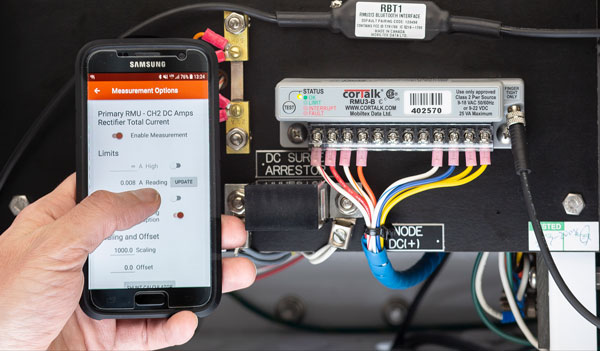
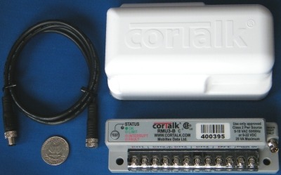
Mobiltex Cathodic Protection Remote Monitoring Unit (CP RMU)
Today’s operators have a range of options to assure that remote monitoring systems can regularly communicate data to their host data collection systems. The availability of conventional cellular networks combined with various commercial satellite systems assures pipeline operators of the ability to communicate with devices in even the remotest of locations. Your monitoring system provider can work with you to select the appropriate communications technology for each CP remote monitoring unit (CP RMU) location.
In addition to choosing how the communication is to occur, another key factor to consider is whether the communications are to be one way (monitoring only) or two-way (monitoring and control). For test station applications where data collection is the goal, one way transmission of the monitoring unit’s data is all that is required. For rectifier units, the ability to control the system output and/or the ability to initiate an interruption cycle for close interval surveys or test station polling purposes necessitates the ability of the cathodic protection remote monitoring unit to receive and act on communications as well as to transmit data.
Software Interfaces – Installing the appropriate CP RMU hardware is just one step in implementing a successful remote monitoring (and control) program. The data must be collected, stored, and accessible for the operator. Sophisticated cloud-based interfaces have been developed that incorporate critical features including firewall-friendly, password protected internet browser access. These systems allow for multiple client user accounts with configurable permission levels and automated alarm and status information including email and text alerts for designated alarm conditions.
In summary, the use of remote monitoring technology is a key component to the successful operation of any modern pipeline integrity management program. While MATCOR has extensive experience with all of the major RMU manufacturers, we have recently teamed up with Mobiltex, a leader in the field of remote monitoring, to bring state of the art technology to the pipeline and cathodic protection industry. Mobiltex’s CorTalk® line of CP RMU units combined with their CorView interface offers all the features necessary to implement a comprehensive, cost-effective, and highly robust cathodic protection remote monitoring program.
Please contact us at the link below if you have questions about cathodic protection remote monitoring, or if you need a quote for services or materials.
Pipeline cathodic protection design for new pipelines may appear to be a rather easy task for anyone with a basic understanding of cathodic protection. However, as with all design efforts there are a wide number of factors that need to be considered for a sound design that meets generally accepted industry practices.
This article highlights 12 things that the pipeline cathodic protection system designer needs to consider when developing a CP system design. This is not intended to be a comprehensive list as every project has its own unique challenges, but these 12 items would all typically have to be addressed during the design phase. It is assumed that the basic pipeline information is already available to the CP designer including pipeline length, pipeline routing and pipeline characteristics (material, wall thickness, coating type, operating temperature, etc.). Armed with this basic information the CP designer should also consider the following in their design efforts.
12 Things to Consider for New Pipeline Cathodic Protection Design
Soil Resistivity is a factor in many of the design calculations and assumptions (e.g. current requirement, anode resistance, attenuation, AC interference, etc…) Actual soil resistivity data should be collected along the proposed route. Learn about soil resistivity testing.
Design current requirement is selected based on the soil type(s) using some accepted industry guidelines taking into consideration the coating manufacturer’s recommended coating efficiency or other industry accepted guidelines. Additional current requirements for mitigating interference currents should be considered based on the designer’s experience.
Distribution of CP System Stations should take into consideration the total current required, the pipeline attenuation characteristics, the availability of power for impressed current cathodic protection systems, varying soil regimes, isolation valves and other factors to determine how many, what size and where each CP System will be located.
Foreign pipelines and other DC interference sources should be evaluated as part of the CP system design efforts and generally warrant immediate mitigation measures or testing and monitoring provisions for observation and assessment.
AC Interference assessment should be performed to determine if there are one or more high risk categories for AC Interference. Should the initial assessment confirm that there is potential for AC Interference an experienced AC Interference and Mitigation specialist would typically use sophisticated AC modeling to assess the risk and propose appropriate mitigation. From a CP perspective, there is a relationship between DC current density and AC induced corrosion risks where too much cathodic protection accelerates the AC induced corrosion rate so care must be exercised by the CP designer to avoid high DC current densities in AC risk areas.
CP Station design includes the type of anode configuration, anode selection, installation methodology, etc… The CP designer will typically provide detailed Bill of Materials as well as CP System issued for construction drawings and construction details showing the location of equipment and providing installation instructions.
Isolation of MLVs and Stations is a key design criterion that impacts the pipeline cathodic protection system design. Some owners are strongly in favor of isolation of MLVs and Stations from their main pipeline while other owners prefer not to isolate and have to maintain isolation and instead require the that CP system be sized to account for losses to current drains.
Power supply type, sizing and selection is another of the decisions that is determined by the CP designer with consideration given to the pipeline owners specifications and preferences. For most pipeline applications, impressed current systems are typical and these require a DC power source. Electrical AC to DC power supplies (“rectifiers”) are the most common power supply but for remote areas with limited AC power availability, alternate power supplies such as solar, wind, fuel cells, thermo-electric generators or other sources may be required.
Terminal piping is often associated with a new pipeline construction project and the pipeline CP system designer must often provide a supplemental design specifically for the terminal or station piping, or account for these in the primary pipeline CP system design
Use of temporary CP systems is often recommended when permanent power may not be available for some time. These typically involve the installation of galvanic anodes strategically along the pipeline.
Provisions for testing and monitoring are critical components to any successful pipeline CP system design. This often includes the use of remote monitoring systems for all of the system power supplies, specialized test coupons for AC and DC Interference, and numerous cathodic protection test stations placed at the appropriate strategic locations to be able to properly test and monitor the CP system performance.
As noted earlier, this is far from a comprehensive list of all of the factors for a specific pipeline CP System design. Every project may have its own unique challenges; however, the 12 items listed above represent a great starting point for any new pipeline cathodic protection system design challenge.
Please contact us at the link below if you have questions about pipeline corrosion, pipeline cathodic protection design, or if you need a quote for services or materials.
 MATCOR provided the plant with a detailed proposal to design and install a complete cathodic protection system using MATCOR’s Replaceable Tank Anode system. The RTA system is based on installing MATCOR SPL
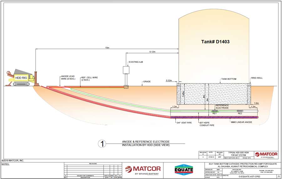
 While the plant conceptually agreed with MATCOR’s solution from a technical perspective, there remained a significant concern within the plant’s operation and safety groups about drilling under this critical service tank and the possibility of a catastrophic event should the drill head drift up to the tank bottom. MATCOR put together a thorough installation procedure including detailed information on the sophisticated drill head tracking systems being utilized to assure that the drill head location was being continuously monitored throughout the bore. Utilizing an experienced local HDD drilling sub-contractor, MATCOR deputed its senior HDD installation drilling supervisor to Kuwait for the installation. Our Senior HDD Drilling Supervisor has completed hundreds of tank HDD installations in the United States and his on-site presence, along with the advanced electronic tracking package being used, assured that each bore went as planned.
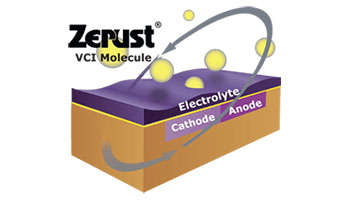
 MATCOR can help.
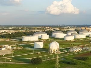 Evan Savant,
  This article describes the components of a
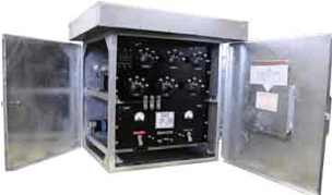

 At MATCOR, we pride ourselves on being a world class manufacturer of unique