How a Utah well project shifted from repeated failure to long-term protection.
A Smarter Approach to Water Well Corrosion
In corrosive groundwater environments like Utah and the broader Western U.S., water well corrosion is not a rare issue—it’s an operational expectation.
Wells fail. Components are replaced. And within just a few years, the same failures can happen again.
For many municipalities and operators, this “run-to-failure” approach has become the default—not because it works, but because until recently, there hasn’t been a viable alternative.
This project represents a shift away from that cycle—toward a more durable, engineered approach to water well corrosion protection.
Project Overview: Rebuilding a High-Risk Well System
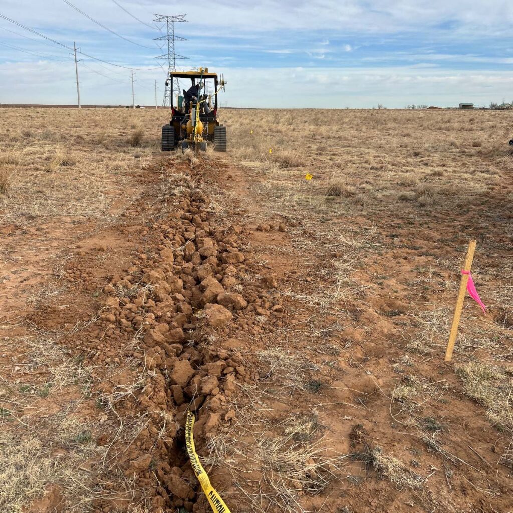
This case study centers on the rehabilitation of a deep municipal water well in Utah, where highly aggressive groundwater chemistry and dissimilar metals accelerate internal corrosion.
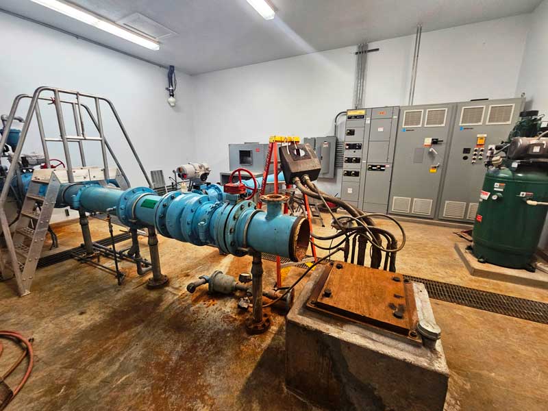
The existing well components had already failed prematurely, requiring a full replacement of internal components. The project team replaced the internal well components while working within an existing steel casing extending approximately 700–800 feet below grade.
New infrastructure included a submersible pump, full-length column piping, and updated internal components designed to improve long-term performance.
At the same time, the team made a critical decision: instead of rebuilding the same system that had already failed, they would address the root cause—internal corrosion.
The Challenge: Water Well Corrosion and Repeated Failure
In high-mineral environments across the region, water well corrosion rapidly degrades internal steel components, which leads to:
- Structural damage to casing and piping
- Sand and debris entering the system
- Premature pump failure
- Repeated, high-cost interventions
In corrosive environments like this, failure isn’t unexpected—it can become a recurring challenge.
“In these environments, you’re not talking about decades—you’re talking about a few years before major components need to be replaced again.” — Corrosion Engineer
Without intervention, rebuilding the system would have simply restarted the same failure cycle.
The Solution: Certified Cathodic Protection for Water Wells
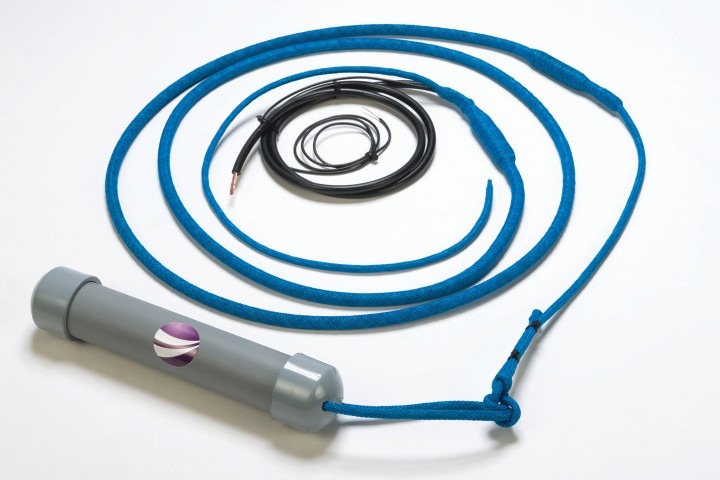
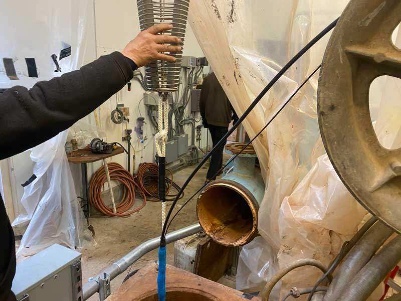
To break the cycle, the project team implemented the MATCOR ORCA Anode System—an engineered solution for water well cathodic protection.
The ORCA Anode System is an engineered, NSF-61-certified cathodic protection system designed specifically for drinking water environments, helping utilities meet strict safety and compliance requirements while providing long-term corrosion protection.
Rather than accepting corrosion as inevitable, the system was designed to protect internal well components, including the casing and riser pipe, from corrosion within the water column.
Delivered pre-configured to match the well’s specifications, the system integrated directly into the rebuild process without requiring field modifications.
Just as important, the system was built for real-world well conditions—tight annular spaces, long vertical depths, and coordination with standard installation crews.
Internal Protection Within a Complete Corrosion Strategy
The ORCA system is designed specifically for internal corrosion protection within the well—targeting the casing and riser pipe inside the water column.
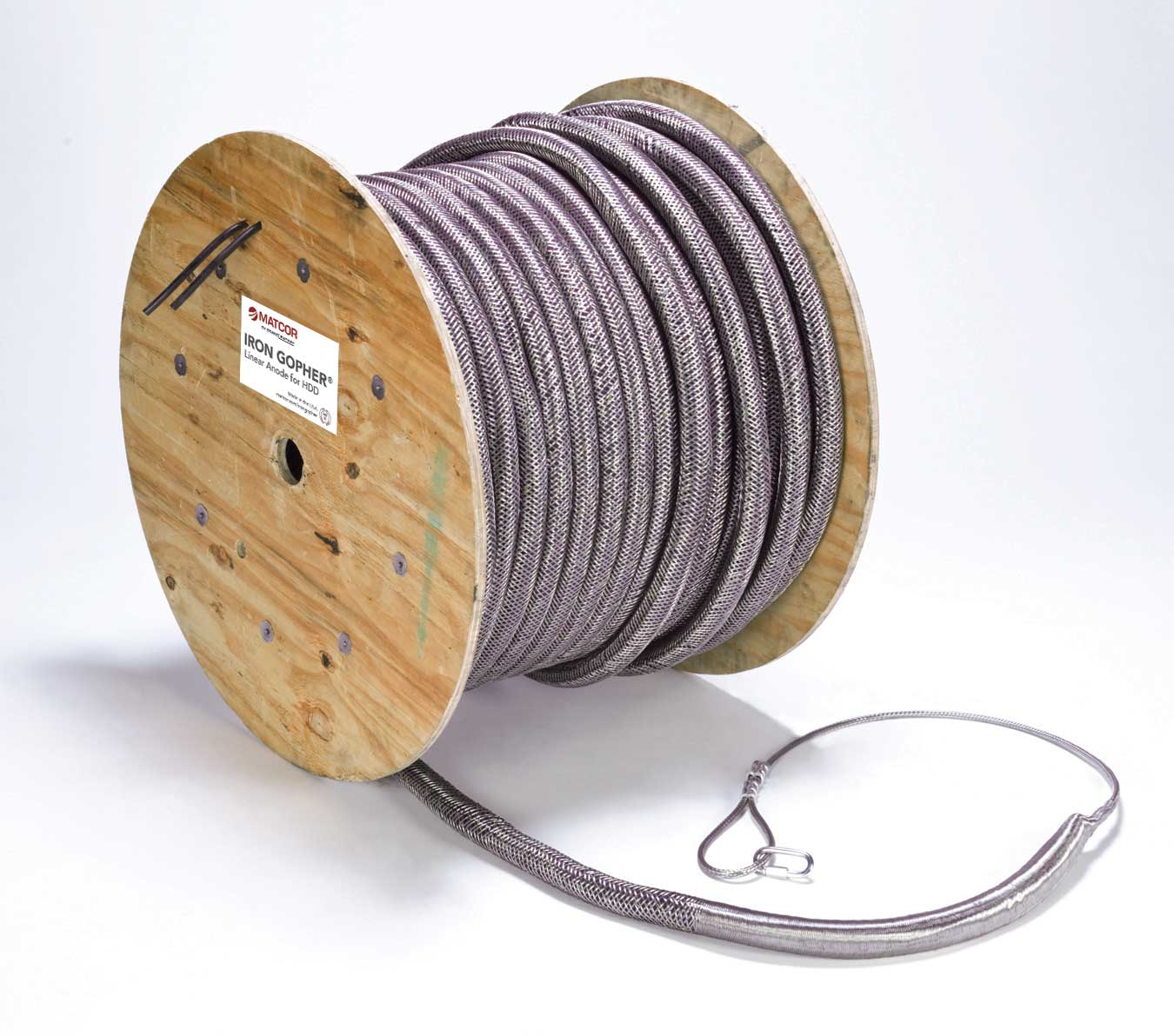
To fully protect well infrastructure, this approach is typically paired with external systems—such as a deep well cathodic protection system designed to protect the outside of the casing.
Together, these approaches create a complete corrosion management strategy that addresses both internal and external risks.
Implementation: Simpler Than Expected
Despite initial concerns, installation proved straightforward.
The ORCA system was installed alongside the pump column during the normal rebuild process, secured at regular intervals as the assembly was lowered into the well.
“The expectation was that this might slow things down quite a bit. In reality, it was maybe half a day—less than we anticipated.” — Corrosion Engineer
The full well installation took approximately one week, with minimal disruption to the project timeline.
This project demonstrates how well casing cathodic protection can be implemented without adding complexity to standard well construction workflows.
Initial Performance Assessment
While long-term data is still being collected, early performance indicators are strong.
Baseline readings were taken prior to system activation, followed by ongoing monitoring as the system came online. Initial monitoring indicates the system is functioning as intended and polarization levels are increasing toward project protection objectives.
“Initial monitoring results are consistent with project expectations and indicate that the system is responding as designed.” — Corrosion Engineer
Due to the amount of exposed steel in the system, full polarization takes time. However, the ability to monitor performance without removing system components provides additional confidence in long-term reliability.
A Shift in Lifecycle Thinking
This project marks a shift from reactive replacement to proactive asset protection.
In some cases , water wells operate on a cycle of failure and replacement within just a few years. With cathodic protection in place, the goal is to significantly extend the lifespan of internal components.
“If this performs the way we expect, it completely changes how these wells are managed long-term.”
The system is designed to provide long-term corrosion protection. Actual performance will depend on site conditions, water chemistry, operating practices, and ongoing monitoring.
Why This Matters for Water Utilities
For municipalities and operators, this project highlights a practical approach to corrosion control in water utilities.
Instead of continuing the cycle of failure and replacement, engineers can implement targeted corrosion protection strategies that extend asset life, reduce long-term costs, improve reliability, and provide ongoing performance visibility.
This approach also aligns with broader water treatment corrosion control strategies focused on long-term asset preservation.
Just as importantly, water utilities and contractors can implement these solutions using standard contractors and existing workflows.
Looking Ahead
Interest in water well corrosion protection solutions continues to grow, particularly in regions where groundwater chemistry accelerates infrastructure degradation.
Following this installation, additional projects are already being designed using similar approaches.
“There’s a lot of interest in this right now, especially in areas where water quality is driving corrosion issues.”
As more systems are deployed, this approach is expected to play a larger role in how utilities manage long-term infrastructure performance.
Conclusion
Break the cycle of repeated failure with a proactive approach to water well corrosion protection.
Request a consultation to evaluate your system and determine the right cathodic protection solution for your water well.