MATCOR’s Ted Huck presented at the Middle East Corrosion Conference on innovative strategies for pipeline rehabilitation, detailing advancements in cathodic protection technology over the decades.
Innovative cathodic protection systems address challenges like aging coatings and poor current distribution. Huck’s presentation explores:
The history and advancements of linear anode technology.
Installation methodologies, including trenching, cable plowing, and horizontal directional drilling.
Case studies demonstrating successful pipeline rehabilitation.
To discover how linear anodes provide localized cathodic protection, enhance current distribution, and extend the lifespan of pipelines without the need for costly recoating, read the full paper or view the presentation.
To get in touch with our team of cathodic protection and AC mitigation experts for more information, to ask a question or get a quote, please click below. We will respond by phone or email within 24 hours. For immediate assistance, please call +1-215-348-2974.
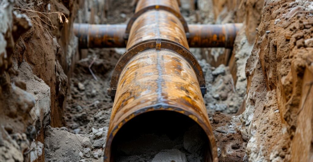
As pipeline coatings age, their ability to prevent external corrosion diminishes. MATCOR highlights cost-effective strategies to rehabilitate pipelines with aging coatings in a Materials Performance article.
From advanced cathodic protection systems (CP) to high-performance recoating solutions, the article explores practical solutions to extend pipeline service life while addressing challenges like soil stress and coating disbondment.
To get in touch with our team of cathodic protection and AC mitigation experts for more information, to ask a question or get a quote, please click below. We will respond by phone or email within 24 hours. For immediate assistance, please call +1-215-348-2974.
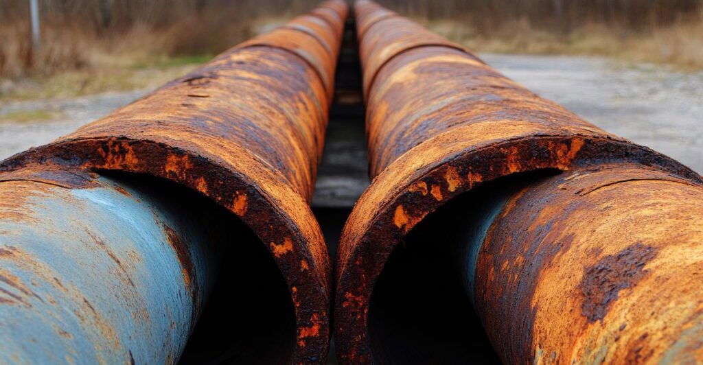
Pipelines are a crucial part of the US infrastructure, but they face a serious challenge: corrosion. This guide explains pipeline corrosion, the different types, and how to prevent it to avoid costly and dangerous failures.
The Problem of Pipeline Corrosion in the United States
The United States has over 2,225,000 kilometers of pipelines transporting oil and natural gas. No other country comes close—Russia, in second place, has approximately 260,000 km. These pipelines are owned and operated by hundreds of companies and regulated by the US Department of Transportation’s Pipeline and Hazardous Materials Safety Administration (PHMSA).
Experts consider pipelines very safe—roughly 70 times safer than trucks1 and 4.5 times safer than rail2. However, many pipelines are at least 50 years old. This increases the risk of corrosion, which threatens their safety and reliability.
Why Pipeline Corrosion Prevention is Critical
Corrosion is a natural process where metal electrochemically reacts with the environment and deteriorates over time. Without regular maintenance and monitoring, this can lead to leaks or even pipeline ruptures.
The good news? Corrosion is completely manageable. By using the right technologies and maintenance practices, pipeline operators can manage corrosion and prevent failures.
Several strategies exist to prevent corrosion, depending on whether it occurs internally or externally.
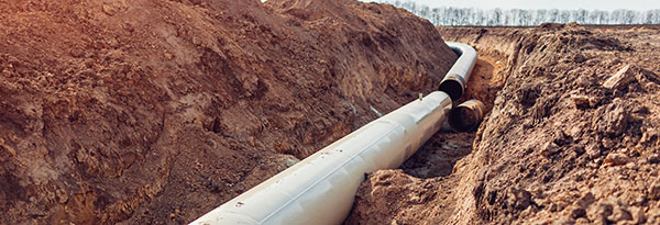
Preventing External Corrosion of Pipelines
The two most effective methods to prevent external corrosion are:
Pipeline coatings: These create a protective barrier between the pipeline and its environment. However, installation can damage them, and they can wear out over time.
Cathodic protection systems: This method uses electrical currents to prevent the metal from corroding and requires frequent testing.
These methods work well, but require regular monitoring and maintenance to remain effective.
Preventing Internal Corrosion of Pipelines
Internal corrosion occurs when contaminants in the oil or gas being transported react with the pipeline. Common contaminants include oxygen, hydrogen sulfide, carbon dioxide, chlorides, and water. The severity of this corrosion is influenced by several factors, including:
The concentration of contaminants
The combination of different contaminants within the pipeline
Operating pressure and flow velocity
Pipeline design and holdup points
Operating temperature
To effectively manage internal corrosion, operators must use a combination of assessment and prevention strategies, including:
Reducing contaminants before they enter the pipeline.
Applying internal pipeline coatings to create a protective barrier.
Injecting inhibitors to minimize corrosion reactions.
Frequent internal cleaning to remove residues.
The Role of Internal Corrosion Direct Assessment (ICDA)
Assessment is the foundation of effective corrosion management. Internal Corrosion Direct Assessment (ICDA) identifies high-risk areas and helps operators prioritize maintenance. ICDA is particularly valuable for:
Evaluating risks based on contaminants, flow conditions, and pipeline design
VCIs are an advanced solution for preventing internal corrosion. They diffuse and bond with internal surfaces to create a protective barrier against water and oxygen.
VCIs are especially effective when used alongside other strategies, such as cathodic protection.
To explore the technology and benefits of VCIs across industries, visit our Vapor Corrosion Inhibitors guide.
While pipeline corrosion is a serious issue, it can be effectively managed through proper monitoring and preventative measures. Whether facing internal or external corrosion, a strong integrity management program is essential to lowering the risk of failure.
To get in touch with our team of cathodic protection and AC mitigation experts for more information, to ask a question or get a quote, please click below. We will respond by phone or email within 24 hours. For immediate assistance, please call +1-215-348-2974.
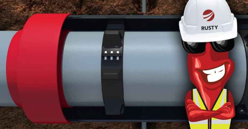
Rusty chats with Ted Huck, Director of Manufacturing and Quality Assurance.
Rusty: Ted, thanks for taking a few minutes to discuss the application of VCI for cased pipeline crossings. First, what is a cased crossing?
Ted: Cased pipeline crossings are a common feature in the industry. They are used primarily at road and rail crossings.
The casing (also referred to as the encasement pipe) is a larger diameter pipe that is designed to take the loading from vehicle or train traffic on the road and absorb/deflect that loading from the carrier pipeline inside the casing.
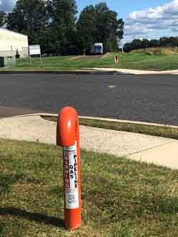
In addition to the encasement pipe and the carrier pipe there are other key elements to a case crossing. Notably, there are non-metallic spacers that position the carrier pipe inside the encasement pipe, and dielectric end seals that prevent the ingress of water and soil. Finally, there are vent pipes on each end of the casing. These provide a warning and route product to a safe location in the event of a pipeline leak inside the sealed casing.
Pipeline Casing Vents on each side of a road crossing in Chalfont, PA
There are tens of thousands of these cased pipeline crossings throughout the United States.
Rusty: So, what are the corrosion challenges with cased crossings? What can go wrong?
Ted: Pipeline operators have found that an inordinate amount of pipeline leaks occur at cased crossings. Therefore, operators are actively looking to eliminate these whenever possible.
It is important to evaluate existing casings periodically. Two mechanisms can adversely affect pipeline integrity at cased crossing locations.
The first is a metallic short. This results from the carrier pipe shifting inside the encasement pipe. It causes a direct metallic contact between the carrier pipe and the encasement pipe.
Shorted casings can significantly impact the cathodic protection system protecting the pipeline. This is due to the encasement pipe drawing CP current away from the carrier pipe. Shorted casings also increase the risk of AC Interference, AC induced corrosion and shock hazards at the above ground vents.
The second casing failure mechanism is related to the integrity of the end seals over time. In many cases, these end seals develop leaks allowing water and soil into the space between the carrier pipe and the encasement pipe. This creates an electrolytic couple. The introduction of these contaminants can lead to accelerated rates of corrosion of the carrier pipe.
Rusty: What are my options if my casing is shorted or the carrier pipe exhibits signs of corrosion?
Ted: You can employ several strategies to address corrosion concerns with cased pipeline crossings:
Excavate ($$$). With this first approach, you dig up the casing and either remove it entirely or repair it. Repairing involves exposing one or both ends to repair the end seals and if necessary, readjust the spacers to clear the shorted condition. This is a construction intensive operation but, in many cases, can restore the cased crossing to an as-new condition.
Fill with Wax ($$). A second approach is to fill the annular space with a high di-electric wax. There are a variety of wax treatment options available. Typically, the wax is introduced through the vents and every effort is made to fill the entire annular space with the wax material.
The wax acts much like a coating covering the carrier pipe and prevents corrosion like a coating system. The industry has found that this is not always a complete solution, since voids in the wax fill can allow pockets of corrosion.
Fill with VCI ($). The third approach is to pump the annular space full of an aqueous gel or powder, or a slurry formulation of corrosion inhibitor material. The corrosion inhibitor is typically a combination of volatile corrosion inhibitor (VCI) and soluble corrosion inhibitor (SCI) that combine to stop corrosion. This method has received industry and regulatory approvals over the past decade and is gaining market share as operators become familiar with the technology and its advantages.
Rusty: How challenging is it to fill a pipeline casing with wax or with VCI?
Ted: Both operations are similar in many respects.
For both wax and VCI filling installations, repairing the existing casing is often the first step. You inspect the end seals and spacers, and where appropriate, remove and replace them.
The interior space between the carrier piping and the casing is flushed clean of dirt and other debris. Once the repairs are complete and the ends are sealed, you calculate the volume of product needed to completely fill the space between the carrier pipe and the casing.
Then the product is prepared according to the manufacturer’s recommendations. Pumping or filling the space is different for each of the type of fill, but both technologies require appropriate equipment and experienced installers.
Wax fills typically use a heated wax product for larger casings. Cold flowing wax can be used on some smaller casings.
For wax fill applications, the space between the carrier pipe and the casings must be completely flushed and cleared out during the repairing of the end seals.
Even with a well-prepared casing, achieving a complete wax fill is very difficult. Voids and gaps are typical.
One published study of 143 wax filled casings found that the average fill was 81%.
For VCI installation plans, the appropriate vapor corrosion inhibitor types and delivery methods are an important considerations. The VCI slurry needs to be mixed properly before being pumped into the casing using the appropriate pumping equipment.
Because VCI applications typically use an aqueous slurry with an experienced installer, VCI is easier to install than a similar wax application. The VCI component is designed to release from the aqueous solution after being pumped into the casing to fill all vapor spaces. Therefore, concerns over gaps and voids are non-existent.
Rusty: What about concerns with bacteria in the space between the carrier pipe and the casing?
Ted: This is an area where the two fill types differ significantly.
For wax filled casings the goal is to completely fill the space with wax displacing or encapsulating any bacteria. However as noted above, areas of incomplete fill or voids in the wax encapsulation can leave space for bacteria to continue to grow.
With VCI, the VCI chemistry increases the pH (9 to 9.5 is typical) inside the casing. This range makes it very difficult for bacteria to grow, while also neutralizing any acid secretions from the bacteria.
Rusty: Can Cathodic Protection help with protecting carrier pipes inside filled casings?
Ted: With wax filled casings, the wax has a high dielectric value and does not allow cathodic protection current to pass.
This prevents the carrier pipe and casing from draining cathodic protection current from the pipeline CP system, but it also provides no protection to the carrier pipe. The VCI gel that sets up is conductive and allows cathodic protection current flow. Some evidence supports the benefit of cathodic protection and VCI working in tandem to prevent corrosion.
Rusty: How can pipeline operators monitor the effectiveness of any cased crossing corrosion solution?
Ted: Most pipelines can be assessed using In Line Inspection (ILI). These pipelines can use smart tools with MFL, and other tools, to assess and monitor corrosion in the carrier pipe with a casing.
For wax filled casings, if ILI is not an option, there are no other good monitoring options. For pipelines that cannot be inspected using smart pig technology, conventional above ground pipeline testing technology is limited.
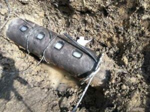
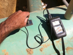
For VCI filled casings, we employ various technologies in conjunction with VCI including coupons, ER Probes and /or UT probes installed between the carrier pipe and the pipeline casing, to monitor the effectiveness of the VCI in the casing. These are installed and connected to RMUs for remote monitoring, or wired to a local junction box for direct reads during surveys.
Rusty: Any final comments on Cased Pipeline Crossings?
Ted: Cased crossings are a challenge for pipeline owners.
Should you have any additional questions, please reach out to a MATCOR account representative for more information. As a full-service corrosion company, we have extensive experience and a wide range of capabilities including both wax and VCI installations for casings.
Have questions or need a quote for corrosion prevention materials or services? Contact us at the link below. For immediate assistance, please call +1-215-348-2974.
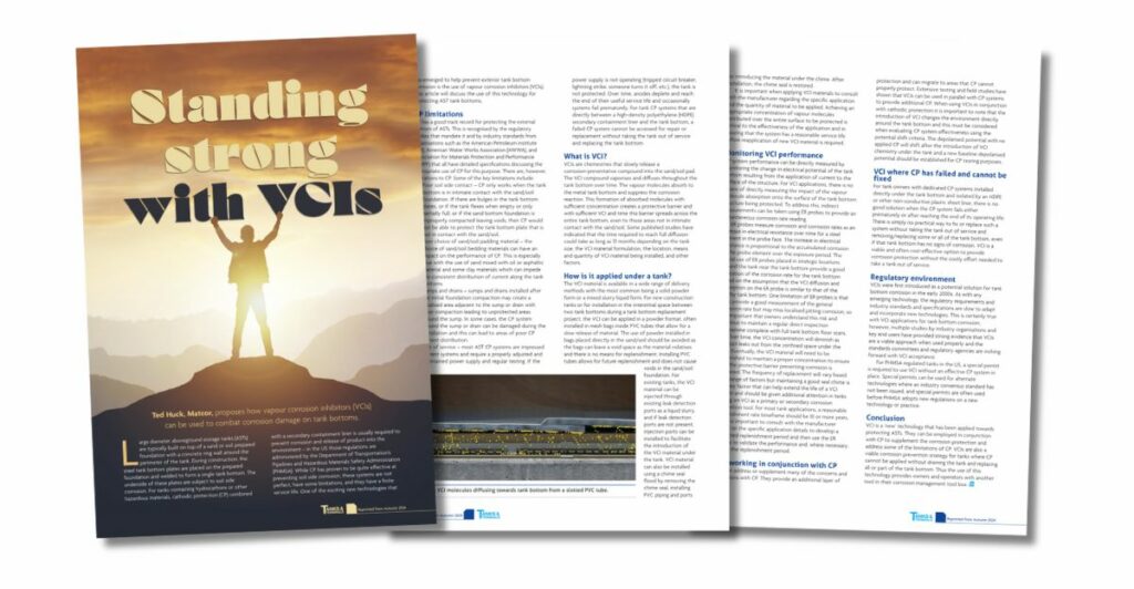
In the Autumn 2024 edition of Tanks & Terminals magazine, MATCOR’s Ted Huck highlights an alternative to traditional corrosion prevention methods for aboveground storage tanks (ASTs): Vapour Corrosion Inhibitors (VCIs).
ASTs, especially those storing hazardous materials like hydrocarbons, are highly susceptible to corrosion on their steel tank bottoms. Typically built on sand or soil foundations with a concrete ring wall, these tanks are vulnerable to soil-side corrosion over time.
While cathodic protection (CP), often combined with a secondary containment liner, has been a standard solution to prevent leaks and environmental damage, it has limitations. VCIs are a newer technology that offers an additional layer of protection for external tank bottoms, addressing some of the challenges CP alone cannot solve.
To get in touch with our team of experts for more information, to ask a question, or to get a quote, please click below. We will respond by phone or email within 24 hours. For immediate assistance, please call +1-215-348-2974.
BrandSafway seminars provide you with in-depth knowledge and practical skills across a wide range of topics. Each seminar includes a 1-hour educational session, a tour, and lunch. MATCOR-specific seminars offer specialized training in cathodic protection and rectifier management:
Cathodic Protection 101: An introduction to cathodic protection, its principles, techniques, and its application in preventing corrosion. This seminar is perfect for those new to the field or looking to refresh their knowledge on preventing corrosion in various structures.
Rectifier School: Comprehensive training on rectifier operation, maintenance, and troubleshooting for effective cathodic protection systems. This seminar is ideal for corrosion technicians responsible for impressed current rectifiers.
AC Interference and Mitigation: A detailed introduction to AC interference and mitigation for engineers and corrosion professionals, focused on practical theory and solutions.
For a full list of BrandSafway’s technical seminars, click here.
To request a lunch and learn seminar, please email matcorsales@matcor.comor call Lisa Porter at 215-327-3002.
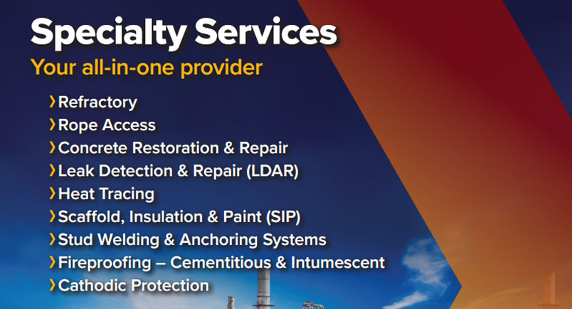
BrandSafway’s Specialty Services
At BrandSafway, we pride ourselves on being the leader in industrial specialty services, offering unparalleled expertise and the largest fleet of scaffolding and access equipment in North America. In addition, MATCOR maintains the largest fleet of construction equipment for cathodic protection projects. Whether your project is large or small, our innovative solutions and dedicated team are here to ensure you meet any challenge safely and efficiently.
As part of BrandSafway, MATCOR specializes in providing advanced corrosion protection, including cathodic protection and AC mitigation solutions. Explore our brochure to learn about how BrandSafway and MATCOR can support your unique needs with industry-leading services and equipment.
For more information, to ask a question, or schedule a seminar, please contact our team of corrosion experts. We will respond by phone or email within 24 hours. For immediate assistance, please call +1-215-348-2974.
The Appalachian Underground Corrosion Short Course (AUCSC) stands as a cornerstone of corrosion protection education, and this year’s event promises to be nothing short of exceptional. The annual gathering is expected to welcome over 1,200 attendees, offering a comprehensive three-day exploration from the fundamentals to advanced knowledge in corrosion mitigation strategies.
Insights from Geoff Rhodes
Geoff Rhodes is the Proposal Manager and a CP field engineer at MATCOR, as well as a dedicated member of the AUCSC General Committee who has invaluable insights into the event. Geoff’s journey with AUCSC began in 2003 as a student, evolving into a pivotal role as a General Committee member in 2004. Over the years, he has transitioned from a student to an instructor, demonstrating a steadfast commitment to advancing the knowledge base within the corrosion protection community.
Contributions to AUCSC
With a wealth of experience under his belt, Rhodes has served as the sub-chair for both the Basic and Technology Today tracks, ensuring the seamless execution of instructional content and the alignment of topics with industry trends.
His contributions have been instrumental in shaping the educational landscape of AUCSC, fostering an environment conducive to learning and professional growth.
Diverse Cathodic Protection Curriculum
The AUCSC curriculum caters to a diverse audience, offering programming tailored to both non-technical individuals and seasoned field technicians and engineers. Attendees can delve into a myriad of topics, ranging from coatings and pipeline integrity management to specialized techniques such as laser ablation of coatings and internal corrosion mitigation.
Outdoor workshops further enrich the learning experience, providing hands-on exposure to cutting-edge corrosion prevention technologies and methodologies.
Expo Highlights
Beyond the classroom, the event features an expo with over 100 vendors, offering attendees the chance to explore the latest products and services in the corrosion protection industry. This convergence of education and networking opportunities makes AUCSC a must-attend event for professionals seeking to stay abreast of the latest developments in cathodic protection and related disciplines.
Rhodes’ Reflections
Reflecting on his tenure with AUCSC, Rhodes emphasizes the profound impact of the event on his professional journey, including staying abreast of trends and networking with peers. His sentiment is echoed by industry stalwarts like George Krewson, a former AUCSC Chairman, who says, “If I had to recommend just one conference for industry education each year, AUCSC would be it.”
Rhodes’ Expertise and MATCOR
Geoff Rhodes’ extensive experience as a participant and contributor to AUCSC underscores the event’s significance within the corrosion protection community. As MATCOR’s proposal manager and field engineer, Rhodes continues to leverage his expertise to drive innovation and excellence in corrosion mitigation strategies. With certifications from AMPP for CP Technologist and Internal Corrosion Technologist, Rhodes exemplifies the commitment to continuous learning and professional development embodied by AUCSC.
Corrosion Protection Education
In summary, the Appalachian Underground Corrosion Short Course is a beacon of excellence in corrosion protection education. Year after year, it remains a vital platform for knowledge exchange, collaboration, and professional advancement—a testament to the enduring legacy of committed industry veterans like Geoff Rhodes.
One of the specialty groups in the BrandSafway Specialty Services Division is Diamond Thermal Systems (DTS), an esteemed leader in reliability and safety. DTS specializes in the evaluation, repair, and long-term care of heat trace systems.
DTS offers customized services to evaluate risks, identify vulnerabilities, and offer comprehensive heat tracing solutions.
What is Heat Tracing?
Heat tracing maintains consistent processing temperatures and protects pipelines and equipment from the adverse effects of cold environments. It is a reliable solution in industrial settings where precise temperature control is crucial for operational efficiency and equipment integrity.
Heat tracing is crucial for safeguarding assets and maximizing productivity across various industries, including oil and gas, chemical plants, and power generation.
The Importance of Heat Trace System Audits
Conducting thorough heat trace audits is the best defense against winter freeze-ups. It reduces the need for costly emergency repairs and promotes proactive system reliability.
DTS heat trace audits comprehensively delve into the critical components of your heat trace system:
Power Distribution Panels
Power Junction Boxes and Heat Trace Cables
Insulation Systems
Post-audit, you’ll receive a comprehensive report detailing system insights, accompanied by visual documentation, findings, and actionable recommendations. Moreover, we provide transparent pricing for turnkey services encompassing heat tracing, insulation, and scaffold services required for any necessary repairs.
Supporting All Heat Trace Systems
At DTS, they proudly support all heat trace systems, regardless of the original equipment manufacturer (OEM). Our commitment to excellence means that irrespective of your system’s specifications, we possess the expertise and resources to deliver optimal solutions.
Your MATCOR representative can help put you in touch with the right contacts at our sister company, DTS, should you have any questions or are looking for heat tracing help.
To get in touch with our team of experts for more information, to ask a question, or to get a quote, please click below. We will respond by phone or email within 24 hours. For immediate assistance, please call +1-215-348-2974.
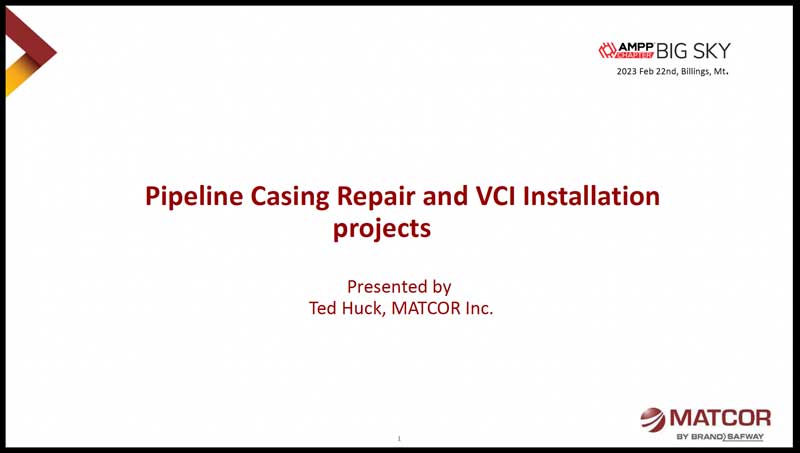
Recently, at the AMPP Association for Materials Protection and Performance Big Sky Section meeting, MATCOR’s Ted Huck presented a case study featuring the casing repair of a high-pressure natural gas pipeline running under railroad tracks and feeding into a power plant.
Following the repair, a vapor corrosion inhibitor (VCI) is installed to prevent corrosion.
Click on the presentation below to check out the development of a casing repair with VCI project scope, removing the short, sealing the casing, and installation of the VCI product through the vent pipe.
To get in touch with our team of cathodic protection and AC mitigation experts for more information, to ask a question, or get a quote, please click below. We will respond by phone or email within 24 hours. For immediate assistance, please call +1-215-348-2974.
In a recent MATCOR blog post, we discussed exothermic welding and pin brazing: Cathodic Protection Pipeline Connections: Exothermic Welding vs. Pin Brazing.
While the article focused on informing, we briefly discussed safety: “both methods are safe procedures when trained personnel follow the correct procedures.” This article will take a deeper dive into the safety considerations and procedures around making connections to pipelines using exothermic welding and pin brazing technologies.
Trained Personnel
Only trained personnel with sufficient experience should make connections to a pipeline. Therefore, short-service and inexperienced personnel should only perform this work if doing so under the direct supervision of an experienced person.
Daily Tailgate Safety Meeting
Note: Different organizations use different terminology, but the basic process is the same.
Every day the team plans and reviews various site activities. At this meeting, they review all applicable instructions, and identify, discuss, and document all potential safety hazards. Each team member signs the document to verify that they understand all safety concerns and their responsibilities.
Safety Hazards
Because pipeline connections are thermal, potential safety issues include flash, burns, accidental ignition, pipe burn-through, pipeline damage, inhalation risks (dust, smoke, ignition product, etc.), and eye injuries.
Therefore, safe entry conditions must exist before team members enter a pipeline or other structure excavation site.
Proper PPE
Personal Protective Equipment (PPE) is non-negotiable when performing pipeline connection work. All team members must:
Wear a hard hat and face shield to protect their head and face.
Wear safety glasses under their face shield with a 5.0 shade rating for pin brazing to protect the eyes.
Wear a particulate mask to protect yourself from grinding dust entering the lungs. Additional breathing protection equipment may be required to protect against inhalation of welding fumes in poorly ventilated areas.
Wear fire-resistant clothing to protect the torso, arms, and legs.
Wear leather gloves free of flammable or thin material to protect the hands.
Wear safety-toed leather boots (no rubber, neoprene, or other flammable materials) to protect the feet.
Positive Identification of the Pipeline
Before any physical work such as excavation, coating removal, heating, grinding, or welding on a pipeline or other structure, the project owner should approve the proposed work and work methods. This step includes positive identification of the pipeline or other asset(s) by the owner or owner’s representative.
Air Monitoring
It is critical to monitor the air at the work site both initially and continually during the work with an LEL gas sensor.
Before proceeding, also test all flanged fittings and valves within 25 feet of the pipeline connection location should be tested with the gas sensor.
Thickness Measurement
Another critical safety step is for trained personnel to test the ultrasonic thickness of the area to be welded. The goal of this testing is to confirm that adequate wall thickness is present to prevent weld “burn-through.”
The table below details the minimum steel wall thicknesses as recommended by ERICO.
Record all results and compare them to nominal wall thickness. If the results indicate possible wall loss due to internal corrosion, the team must not proceed with exothermal welding.
Note: Do not perform exothermic welding if you measure a difference of 20% or more from nominal thickness or readings below 0.110” are measured.
Nominal Pipe Size
Schedule
Wall Thickness
0.5″
40
0.109″
0.75″
40
0.113″
1-2″
10
0.109″
2.5-4″
10
0.112″
5-10″
5
0.109″
10+”
5
> 0.109″
Coating Removal and Surface Profiling
Before coating removal, the pipeline operator should confirm that the coating is asbestos-free. Alternative removal procedures and safety precautions are required if the coating contains asbestos. A face shield should be used whenever grinding activities are performed.
Additional Considerations and Precautions
Explosive Internal Conditions
For active gas and liquids pipelines, the fluid velocity and lack of oxygen prevent the internal fluid from igniting due to the temperature rise in the pipeline wall. However, out-of-service lines are likely not fully purged, and oxygen and vapor may ignite inside the pipeline or vessel; purge these lines before proceeding.
Only perform exothermic welding on standard-thickness steel piping or vessels. Aluminum, copper, and thin-walled steel pose a greater risk of burn-through.
Don’t use anything larger than a 15-gram charge when welding onto steel fuel piping or vessels. Other structures, such as ductile iron pipes, may be more tolerant of more significant weld charges.
As you can see, both methods of pipeline connections are safe. However, adequately trained and experienced people must use the proper procedures and take the appropriate precautions.
To get in touch with our team of cathodic protection and AC mitigation experts for more information, to ask a question, or get a quote, please click below. We will respond by phone or email within 24 hours. For immediate assistance, please call +1-215-348-2974.