 This article describes the components of a cathodic protection rectifier, and when to use oil cooled cathodic protection transformer rectifiers vs. air cooled rectifiers.
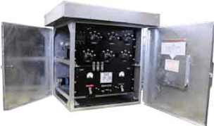
When it comes to cathodic protection power supplies, conventional transformer rectifier circuits have long been employed by the cathodic protection industry for impressed current CP systems. These power supplies (commonly referred to as rectifiers in the CP world) consist of three main components; the transformer, the rectification stack, and a cabinet to house these components. The transformer takes the input AC voltage on the primary side and controls the output AC voltage on the secondary side. The rectification stack, typically silicon diode stacks which have largely replaced older less efficient selenium stacks, convert the AC input wave form into a DC wave form by cycling the AC flows in one direction and blocking in the other. Additional components typically include circuit breakers, fuses, voltage and current output meters, lightning arrestors, surge suppressors, transformer tap bars, and monitoring systems.
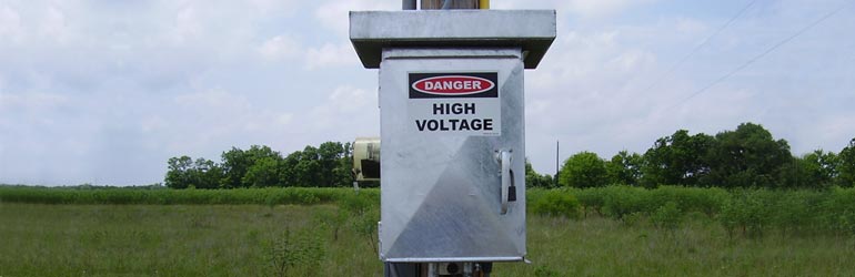
The majority of these Rectifiers are housed in air-cooled NEMA 3R enclosures – these enclosures are typically constructed of hot dipped galvanized steel, aluminum, stainless steel or painted steel. NEMA 3R enclosures are intended for outdoor use. They provide a degree of protection against falling rain and ice formation but are not completely water tight or weather proof and could be subjected to beating rain or streams of water, under certain conditions, entering the enclosure. This is the most common type of rectifier enclosure in the industry.
When and Where to Use Oil Cooled Cathodic Protection Transformer Rectifiers
For some applications; however, the use of air cooled NEMA 3R enclosures is not recommended or not suitable. The three most common reasons not to use air-cooled NEMA 3R enclosures are:
- Rectifier transformer size is too large to support an air cooled enclosure. For a small percentage of impressed current CP systems where the power requirements (measured in DC Watts) are sufficiently high that the cooling capacity of the enclosure is insufficient for the heat generated by the transformer (typically anything more than 12kW for single phase and 18kW for three phase.)
- Severe environment locations where high humidity, dust or other situations could shorten the life of a standard air cooled rectifier. Marine and near shore applications often fall into this category.
- The enclosure must be in a hazardous classified location requiring Class 1 Div. 2, Group D compliant enclosure – commonly referred to as Explosion Proof.
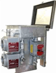
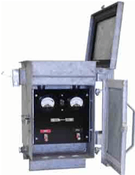
For these applications, oil cooled cathodic protection transformer rectifiers are typically specified. As implied in the name, the oil cooled rectifier utilizes an enclosure that has a sealed reservoir which houses the transformer and transformer tap bars and is filled with a special transformer oil. The transformer oil provides better heat transfer and dissipation and the larger case facilitates improved heat removal.
It is very important to note that standard oil cooled rectifiers are NOT explosion proof. For an oil cooled rectifier to be considered Explosion Proof, the components that are not immersed in the transformer oil reservoir must be housed in special Explosion Proof fixtures. Simply specifying oil cooled when ordering a rectifier does not satisfy the requirements for locating the rectifier in a hazardous Class 1 Div.2 location without also including the additional provisions required for the explosion proof fittings.
To get in touch with our team of cathodic protection experts for more information, to ask a question or get a quote for cathodic protection materials or related construction services, please click below. We will respond by phone or email within 24 hours. For immediate assistance, please call +1-215-348-2974.
Contact a Corrosion Expert
 As we roll out our new fleet of construction equipment across our operating regions, that grin on our crew members’ faces is not from the new car smell in their truck – it’s that feeling of rolling up to the job site with state-of-the-art new construction equipment that looks great and performs even better. We’ve invested heavily in improving our construction fleet and listening to our crews and our customers.
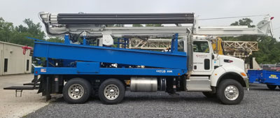
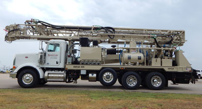
 Our new drilling rigs are bigger and faster and incorporate the latest technologies to assure that we have the right equipment for the job. Outfitted for both air and rotary mud drilling operations, these rigs are ready to rumble. The impact for our crews and customers includes:
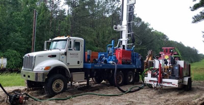
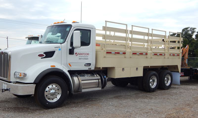 Our new fleet of water trucks were specifically designed by MATCOR for deep anode installation projects. These new trucks enable us to reduce our crew footprint and consolidate our vehicle count by combining our water truck, coke pump and material truck into a single multi-purpose vehicle. Reduced vehicle traffic greatly lowers impact on the customer site and access roads. It also reduces our environmental emissions impact while eliminating one additional driver/crew member. Innovative equipment design makes us safer and more competitive.
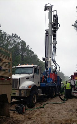
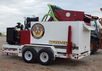 Portable pits are the pits – MATCOR is moving towards a new state of the art mud cleaning and handling system that eliminates the need for earthen pit or portable pits. Our new
 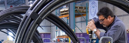 At MATCOR, we pride ourselves on being a world class manufacturer of unique
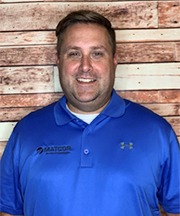 Meet Dan Vallot, our newest Account Manager. Dan is based at our Gonzales, Louisiana, office and covers the Gulf Coast states of Louisiana, Mississippi, Alabama, Florida and Georgia. Dan comes to us from Versa Integrity Group where he sold NDT services. Prior to that, he sold specialty mechanical services for Carber. Dan has 3 children, the oldest is attending LSU. In his free time he enjoys being with his family, cooking and gardening. He is also the Director for Industry of Faith Louisiana, a faith-based organization that provides support for oil and gas workers in the state of Louisiana. Please let Dan know how he can assist you to solve your corrosion problems.
 Dave comes to us from NCSG Crane and Heavy Haul, where he sold crane services primarily to oil and gas companies and industrial facilities for maintenance and new construction. He is also a United States Operation Iraqi Freedom Veteran of 7-1/2 years and has a Bachelors Degree in kinesiology and physical therapy. Dave will be based at our new Casper, WY office and will cover the states of Arizona, Colorado, Idaho, Montana, North Dakota, Northern New Mexico, South Dakota, Utah and Wyoming.
 Based out of our Wadsworth Street facility in Houston, Ryan will cover the greater Houston area of the Gulf region. Before joining MATCOR, Ryan worked in Business Development for OES Oilfield Services, selling to offshore drilling companies.
 Trey joins us to cover the Mid-Continent region including the states of Missouri, Kansas, Nebraska, Oklahoma, Arkansas and the Texas Panhandle and will be based out of our Guthrie office. Trey is a United States Army Operation Enduring Freedom Veteran of 6 years. He has a BS in Business Management, minoring in Finance, and an MBA. He has 10 years’ experience in the midstream industry with T.D. Williamson and Nalco Champion.