The richest man in Africa, Aliko Dangote, undertakes $12B project including 153 ASTs
Chalfont, PA (April 2019) – MATCOR, Inc., the trusted full-service provider of proprietary cathodic protection products, systems, services and corrosion engineering solutions announced that it recently completed shipment of over 500,000 linear feet (150+ km) of its SPL™-FBR linear anode product along with other ancillary materials for 153 above ground storage tanks (ASTs) in Africa.
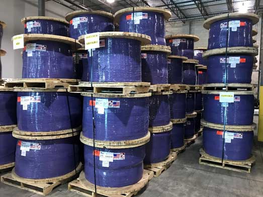
Tank anode system materials prepped for export at MATCOR’s Chalfont PA facility. Over 520 reels of anode material have been shipped to Nigeria.
The anodes, which will prevent tank bottom corrosion, are part of an ambitious refinery project undertaken by Aliko Dangote, Africa’s richest man. The tanks are being erected on over 6,000 acres of swampland outside of Lagos, Nigeria.
MATCOR was selected for this project due to quick delivery and the company’s unique linear anode design, which does not require field splicing and saves significantly on installation time and costs.
“The ability to manufacture the large quantity of custom length linear anode segments in a very compressed time frame was key to meeting the tank contractor’s needs,” noted Ted Huck, Director of Manufacturing and Quality Assurance for MATCOR. “Our team handled a very complex order with a very tight delivery schedule while maintaining world class quality.”
Learn more about the project in our recent blog post.
This month MATCOR will ship the final tank anode system assemblies for Africa’s most audacious industrial project. The project is being undertaken by Aliko Dangote, Africa’s richest person, and when completed this $12 billion Dangote oil refinery could, according to a 2018 New York Times article, “transform Nigeria’s corrupt and underperforming petroleum industry. Planned as the world’s largest refinery…should process 650,000 barrels of crude oil daily.” With Nigeria poised to become the world’s third most populous nation by 2050 (surpassing the USA) and having Africa’s largest economy, this project is being touted as a milestone achievement in what many are dubbing the African Century.
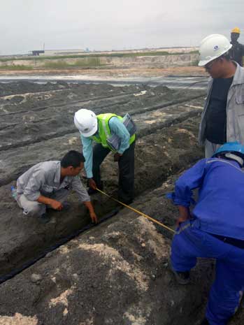
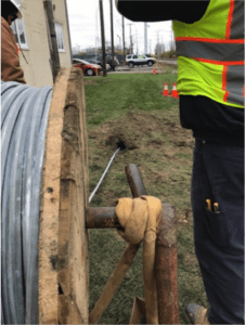
MATCOR Field Engineer E.Gopal (yellow vest) at Lagos site inspecting tank anode system installation
As part of this ambitious refinery project, a total of 153 above ground storage tanks for crude oil, refined and intermediary products up to 92m in diameter (300 ft) are being erected on the 6,180 acres of swampland just outside of Lagos, Nigeria. MATCOR’s innovative tank anode system technology using linear anodes was selected by the project’s EPC contractor, Engineer’s India Limited, as the design basis for the cathodic protection for the project’s above ground storage tanks. Working closely with both the owner’s Indian based engineering team and the EPC contractor, MATCOR was successful in identifying the key tank contractors that would be bidding the tank erection and supplying the cathodic protection systems as part of their specifications.
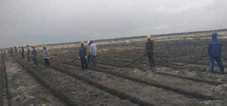
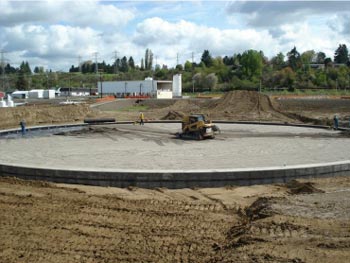
Linear Anode being installed on large crude oil storage tank foundation
Ultimately, MATCOR was successful in securing contracts to provide the linear anodes for each of the three tank packages, one from a Chinese contractor and two from a UAE based contractor.
Tank anode system materials prepped for export at MATCOR’s Chalfont PA facility. Over 520 reels of anode material have been shipped to Nigeria.
In total, MATCOR has supplied over 500,000 linear feet (150+ km) of our SPL™-FBR linear anode product along with other ancillary materials for the under tank cathodic protection systems over an 18-month period. With all the anodes having been manufactured in MATCOR’s ISO 9001 certified Chalfont PA facility, MATCOR continues to be the global leader in the manufacturing of impressed current linear anodes for above ground storage tank cathodic protection.
Have questions about tank corrosion protection, or need a quote for services or our tank anode system? Contact us at the link below.
Specifying the ideal sand bedding supports tank corrosion protection and a long tank bottom service life.
For new construction tank projects and for retrofits of existing tanks, it is common practice to install clean washed sand as the pad upon which the tank bottom is fabricated. The use of oil sand, crushed stone, asphalt, or other materials directly under the tank bottom should be avoided, as these hinder effective tank corrosion protection. This article provides guidelines to the specifications for the sand bedding materials. These guidelines are based on providing a low corrosivity environment compatible with cathodic protection to assure a long service life of the tank bottom.
Economic Considerations
For a typical 150-foot diameter tank using 12 inches of sand bedding the quantity of sand that is required is approximately 17,679 cubic feet of sand which is roughly 883 tons. The cost of the sand, including delivery, is a significant cost and far exceeds the cost of cathodic protection– especially if the sand specifications are quite stringent and require sourcing sand that requires significant transportation. Some consideration can be given to relaxing the sand recommendations, even if that warrants increasing the cathodic protection requirements, should there be a significant cost impact to complying with the sand specifications – consult your cathodic protection designer.
Recommended Sand Properties
The table below summarizes the recommended sand properties to support aboveground storage tank corrosion protection.
Property
Recommended Value
Resistivity (ohm-cm)
20,000 – 100,000
pH
> 6.5
Chlorides (ppm)
< 10
Sulfates (ppm)
< 200
Sulfides (ppm)
< 0.1
Particle Size
100% pass through #4 Sieve
Soil Resistivity
The best proxy for determining corrosivity of sand materials is the electrical resistivity of the sand. Clean washed sand typically has resistivity values more than 20,000 ohm-cm and in some cases can exceed 100,000 ohm-cm. The higher the resistivity of the sand, the lower the corrosivity of the sand; however, when designing cathodic protection, the higher the sand resistivity the greater the impact on the overall system resistance and the electrical power required for the cathodic protection system. API Recommended Practice 651 Cathodic Protection of Aboveground Petroleum Storage Tanks provides the following table classifying resistivity of soil/sand.
Measuring pH indicates the hydrogen ion content of a soil. Corrosion of steel is fairly independent of pH when it is in the range of 5.0 to 8.0. The rate of corrosion increases appreciably when pH is < 5.0 and decreases when pH is> 8.0. pH may be determined in accordance with ASTM G 51 or equivalent
Chlorides
Chlorides will affect the resistivity of soil, and act as a depolarizing agent which will increase the current requirement for cathodic protection of steel. Pitting corrosion on steel can begin at chloride levels of 10 ppm. Chloride content may be determined in accordance with ASTM D 512 or equivalent.
Sulfates
Sulfate levels >200 ppm frequently indicate high concentrations of organic matter. Sulfate content may be determined in accordance with ASTM D 516 or equivalent.
Sulfides
Sulfide levels > 0.10 ppm may indicate that sulfates have been reduced by bacteria. Sulfide content may be determined in accordance with EPA 0376.1 or equivalent.
Particle Size
The sand bedding material should be clean of rocks, clumps and other debris and for clean sand capable of passing through a #4 sieve, for washed river sand an alternative acceptable particle size is 100% pass through a 3/8” sieve.
Sand Depth of Cover
For new construction tanks, the typical design is to provide a minimum of 12 inches (30 cm) of sand cover; however, for tank bottom retrofits it is quite common to provide 6 inches of sand (15 cm) for double bottom installations or for applications where the existing bottom is removed, and the top layer of the underlying soil foundation is being removed.
Have questions about tank corrosion protection, or need a quote for services or cathodic protection design and materials? Contact us at the link below.
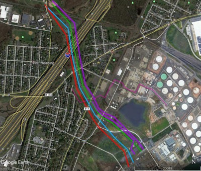
MATCOR provides a full range of AC Mitigation capabilities including AC Modeling and Design engineering services, supply of our proprietary Mitigator® engineered AC grounding system, and an entire construction services organization capable of a wide range of AC Mitigation installation services. Two current projects highlight our construction service capabilities with regards to AC Mitigation. The first project involves several miles of zinc ribbon installation for an AC mitigation system in a congested suburban and urban environment using horizontal directional drilling (HDD) equipment. The second application is in a highly rocky environment in West Texas that requires the use of specialized rock trenching technology for zinc ribbon installation.
Zinc Ribbon Installation Using HDD in a Congested Environment
Figure 1 – Zinc ribbon being installed through HDD bore hole
This project in northwestern Ohio involved the zinc ribbon installation over several miles using one of MATCOR’s in-house horizontal directional drilling crews. The project required horizontal directional drilling to minimize surface disturbances due to the congested area.
With any typical AC Mitigation installation there are numerous precautions that must be taken to assure a safe installation. This starts with a thorough pre-construction safety review to develop the project site-specific health and safety plan. Each crew member participates in a daily safety meeting to review the day’s planned activities and address all safety concerns in advance of performing any work. Each crew member is required to have the appropriate operator qualifications and site-specific safety training as identified by MATCOR and the pipeline owner.
Figure 2 – HDD bore in process
Prior to any other construction activities, the first task is to perform a thorough line locating including potholing (excavation of the top of the pipe). This is to physically assure that the location of the pipeline(s) being mitigated is accurately marked to avoid any risks associated with construction activities in close proximity to the pipeline.
Once the pipeline has been physically located and properly flagged, each individual bore must be planned. The route of the bore is assessed prior to boring activities commencing. The bore planning includes:
Identifying entry and exit points
How the bore is to be tracked
Special precautions that might be needed to maintain the bore during the ribbon installations
How the cuttings will be captured, stored and removed
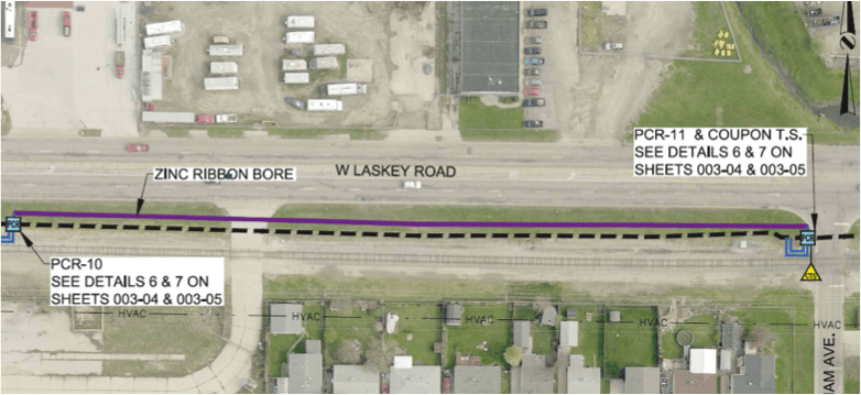
Figure 3 – Zinc Ribbon Bore – AC Mitigation design detail – note rail line to the South
As with any construction project, logistics and project management are key to the successful execution of the project. Working in conjunction with the owner and their designated project inspector to assure that the work is performed safely and in accordance with the AC Mitigation design requirements. For the project in Ohio, some additional complications included difficult weather conditions and working in close proximity to a railroad which requires additional permitting and coordination with the railroad. In some locations, traffic control was also required during the installation work.
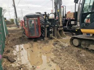
Rocky Conditions in West Texas
Figure 4 – Rock trenching in a difficult West Texas environment
Another project that MATCOR is currently completing involves the installation of approximately 15 miles of zinc ribbon in West Texas. The original installation plan called for the use of a cable plow to install the zinc ribbon mitigation wire; however, for large stretches of the installation, the rocky conditions forced MATCOR to switch from the planned cable plow to a high-powered rock trencher to cut through the difficult rocky terrain. This project illustrates the importance of using the right equipment to overcome difficult installation challenges. In some cases, being able to adapt to adverse conditions requires a change in construction methodologies and for this project, MATCOR’s ability to react and make equipment changes allowed the project to proceed on schedule with minimal customer impact.
This project also requires the use of HDD for one specific mitigation segment, as the pipeline traverses a cotton field which includes a buried drip irrigation system. The use of HDD is required to prevent any damage to the drip irrigation system during the AC Mitigation zinc ribbon installation. Coordinating the installation schedule around the cotton crop cultivation added another logistical challenge to the project.
Whatever your AC Mitigation challenge might be, MATCOR’s construction teams are able to work with our clients and their project needs to assure a safe and cost-effective installation project.
Have questions about zinc ribbon installation, or need a quote for AC mitigation materials or services? Contact us at the link below.
Engineers rely on soil resistivity testing as one of the most critical steps in designing an effective cathodic protection system. This soil resistivity test method provides the data needed to evaluate soil conditions and design reliable corrosion protection systems.
Accurate soil resistivity data directly impacts the anode selection, system performance, and long-term corrosion control. Incomplete or inaccurate data leads to underperforming systems, premature failure, and costly redesigns.
It also serves as a foundational input to cathodic protection design, helping engineers develop systems based on accurate field data.
This article explains how engineers perform soil resistivity testing, when they need it, and how the data supports real-world cathodic protection design decisions.
What is Soil Resistivity Testing and Why It Matters for CP Design
One of the most important design parameters when considering the application of cathodic protection for buried structures is the resistivity of the soil. Engineers use soil resistivity testing to assess the corrosivity of the environment surrounding buried structures.
Soil conditions directly influence:
System type
Anode quantity
System configuration
Without accurate soil resistivity data at both the structure and proposed anode locations, engineers risk designing ineffective cathodic protection systems that require costly remediation after commissioning.
How Soil Resistivity Determines Soil Corrosivity
Soil resistivity is the primary diagnostic factor for evaluating soil corrosivity. When engineers perform soil resistivity testing, they also consider factors such as:
Soil composition
Moisture content
pH
Chloride and sulfate concentrations
Redox (oxidation-reduction) potential
While comprehensive soil analysis may be required for failure investigations, soil resistivity testing provides the most practical and widely used field measurement for cathodic protection design.
Soil Resistivity Ranges and Corrosivity Classification
Below is a typical chart correlating soil resistivity with soil corrosivity.
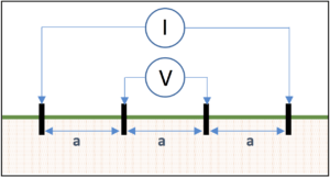
While there are several methods for measuring soil resistivity, the most common field testing method is the Wenner four-pin method (ASTM G57).
This method uses four metal probes, driven into the ground and spaced equidistant from each other. The outer pins are connected to a current source (I) and the inner pins are connected to a volt meter (V) as shown in Figure 1.
Soil Resistivity Formula and Calculation
Engineers convert measured resistance (R) into resistivity using a standard soil resistivity testing formula:
ρ=2×π×ax 30.48 cm/ft. ×R = 191.5 x a x R
Where:
ρ = soil resistivity, Ω-cm
a = probe spacing, ft.
R = measured resistance, Ω
How Probe Spacing Relates to Testing Depth
Each probe spacing represents the average soil resistivity to a depth equivalent to that spacing. For example, a 5-foot spacing reflects the average resistivity at approximately 5 foot deep.
For shallow anode placement, it is usually sufficient to take reading readings at 2.5 ft, 5 ft, 10 ft, 20 ft, 25 ft. For deep anode applications, soil resistivity measurements may be recommended at much deeper depths corresponding with the anticipated depth of the deep anode system.
Understanding Soil Layer Effects in Resistivity Testing
It is important to note that the soil resistivity values generated from the four pin testing represent the average soil resistivity from the earth surface down to the depth, and each subsequent probe spacing includes all of the shallow resistance readings above it.
Using the Barnes Method to Interpret Layered Soil Resistivity
To isolate resistivity at specific depths, engineers apply analytical techniques such as the Barnes method. This method:
Converts resistance to conductance
Evaluates incremental changes between readings
Calculates true layer resistivity
Engineers rely on this approach to identify low-resistivity zones that significantly impact cathodic protection performance.
Example of Layered Soil Analysis
For the Barnes analysis below, the data shows that a low resistance zone exists between 60m depth and 100m depth.
TEST DATA
BARNES ANALYSIS
Spacing a
(m)
Resistance
(ohms)
Conductance 1/R
(Siemens)
Change in Conductance
(Siemens)
Layer Resistance
(ohms)
Layer Resistivity
(Ohm-m)
20
1.21
0.83
—
1.21
152
40
0.90
1.11
0.28
3.57
441
60
0.63
1.59
0.48
2.08
264
80
0.11
9.09
7.5
0.13
17
100
0.065
15.38
6.29
0.16
20
120
0.058
17.24
1.86
0.54
68
Choosing the Right Soil Resistivity Testing Equipment
Engineers must use the right soil resistivity testing equipment to collect accurate field data. Electrical noise from power lines, substations, railroad tracks, and many other sources can distort readings if not properly managed.
Modern soil resistivity meters include filtering capabilities to reduce interference and improve measurement accuracy.
High-Frequency Soil Resistivity Meters for Shallow Testing
High-frequency meters operate above 60 Hz and should be limited to data collection of about 100 feet in depth.
This is because they lack sufficient voltage to handle long traverses and they induce noise voltage in the potential leads which cannot be filtered out as the soil resistivity decreases and the probe spacing increases.
Engineers commonly use these meters for:
Shallow testing
Corrosion assessment
Shallow anode design
They offer a cost-effective solution but have limitations in deeper applications.
Low-Frequency Soil Resistivity Meters for Deep Testing
Low-frequency meters operate between 0.5 to 2.0 Hz and support deeper soil resistivity testing.
These meters:
Handle large probe spacing
Provide superior noise filtering
Deliver accurate readings at greater depths
Engineers typically prefer low-frequency meters for deep anode cathodic protection design.
Field Best Practices for Accurate Soil Resistivity Testing
Accurate soil resistivity testing depends on proper field procedures and site conditions.
Select the Right Testing Location. The use of the Wenner four pin testing method requires sufficient open area to properly space the pins to collect data to the depths necessary. For deep anode cathodic protection systems this would require a minimum of three times the anticipated anode system depth.
Avoid Interference from Buried Piping and Other Metallic Objects. The presence of any buried metallic structures (piping, conduit, reinforced concrete structures, grounding systems, etc…) provides low current paths that could cause a short-cutting effect that would distort the resistance readings and yield an erroneous soil resistivity reading.
Control Probe Depth for Accurate Readings. It is important that the probes are properly inserted into the earth. For shallow resistivity readings, probes that are driven too deep can impact the shallow readings. Ideally, the pins should be no deeper than 1/20th of the spacing between the pins and no more than 10 cm (4 inches) deep.
Minimize Electrical Noise During Testing. Soil testing should not be performed directly under high voltage transmission systems or near other outside sources of current in the soil such as DC light rail systems.
Record Soil Conditions and Environmental Factors. It is important that the location of the testing is accurately recorded along with the soil conditions and temperature at the time of testing. Testing should not be performed in frozen soil, or during periods of extreme drought or abnormally wet conditions.
When to Use Professional Soil Resistivity Testing Services
Professional soil resistivity testing for cathodic protection becomes critical when projects require accurate field data to support system design, deep anode installations, or corrosion troubleshooting.
Engineers rely on experienced providers to perform soil resistivity tests, interpret layered soil conditions, and deliver reliable data for CP design.
Working with a qualified team helps:
Reduce design risk
Improve system performance
Avoid costly rework
Key Takeaways: Soil Resistivity Testing for CP Design
Soil resistivity testing provides the most reliable indicator of soil corrosivity for buried structures and plays a critical role in cathodic protection system design.
Engineers most commonly use the Wenner four pin method to perform soil resistivity tests. When properly collected and interpreted, teams can design CP systems that perform reliably and efficiently.
Iron Gopher® is only linear anode designed for cathodic protection in horizontal directional drilling applications
KENNESAW, Georgia, Sept. 19, 2018 — MATCOR, a BrandSafway company, recently earned a design patent for its Iron Gopher®, a linear anode designed to prevent corrosion through cathodic protection in horizontal directional drilling (HDD) applications. With a braided stainless steel jacket for linear anode protection during installation and a built-in pulling loop for connecting to the drilling head, the Iron Gopher provides approximately 200 percent more pulling strength than traditional anodes used in HDD applications.
It is available in standard and dual-end models, which can both be connected to a DC power source for active cathodic protection with a current. The standard model is used for most cathodic methods, such as roads, streams and property crossings, and the dual-end model is typically used under tank operations or anywhere it is not possible to connect both ends of the linear anode.
“We developed the Iron Gopher with installation costs and timelines at the forefront, focusing on strength to reduce the risks associated with the linear anode breaking during installation,” said Ted Huck, one of the Iron Gopher inventors and vice president of technical sales for MATCOR. “It also makes job sites—and utilities and pipelines—safer by using cathodic protection to decrease the chance of failure due to corrosion that could cause gas leaks or other potentially catastrophic events.”
The Iron Gopher was invented by Ted Huck; William Schutt, MATCOR founder; and Knut Fenner, former director of business development at MATCOR.
“MATCOR is an innovation leader in the corrosion and cathodic protection industry with its ongoing R&D, proprietary products, service and client-focused cloud technology,” Bob Burns, president of Midstream said. “The Iron Gopher is just another example of how we are continually raising the standards within the corrosion industry and ultimately providing the best solutions to our clients.”
MATCOR, Inc. is a BrandSafway company and a leading cathodic protection and corrosion prevention engineering design firm, providing environmentally beneficial systems and services to global clients for more than 40 years. An ISO 9001:2015 certified expert in the field of cathodic protection, MATCOR offers proprietary corrosion protection design, engineering, manufacturing, installation, cathodic protection testing, annual surveys, maintenance and complete corrosion protection project management. MATCOR specializes in protecting the infrastructure of the oil and gas, utility, transportation and construction industries. To learn more about MATCOR, please visit www.matcor.com or call 1-215-348-2974.
About BrandSafway
With a commitment to safety as its foremost value, BrandSafway provides the broadest range of services, products and solutions, with the greatest depth of expertise, to the industrial, commercial and infrastructure markets. A portfolio company of Clayton, Dubilier & Rice, BrandSafway offers access, industrial services and forming and shoring solutions to more than 32,000 customers through a workforce of approximately 35,000 employees, who support our network of 350 strategic locations across 30 countries. With its global footprint, rigorous operating processes and extensive service offerings — a full range of work access, insulation, coatings, specialty industrial services and forming and shoring solutions — BrandSafway supports customers’ maintenance and refurbishment needs as well as new construction and expansion plans. Today’s BrandSafway — large enough to leverage economies of scale to increase safety and productivity, while also remaining nimble and responsive — delivers unmatched service with local labor and management.
We’ve talked about AC Interference and we’ve talked about AC Modeling. The topic of our newest training video is AC Mitigation. The video is about 9 minutes long and we’ve included timeline indicators below so you can easily find your topic of interest in the video.
The goal for AC mitigation is to reduce your fault condition stress values to protect against stress coating damage and arcing potentials (arcing is less common because you need to be very close to the pipeline for arcs to appear). This includes:
Reducing current density below your threshold value. Typically in the US we use 20 amps per meter squared for a one CM2
Maintaining AC step and touch potential below 15 volts so that people working in and around pipeline areas are not subject to shock due to a fault condition
AC Modeling Aids in Predicting Conditions [0:55]
We use AC modeling to provide predictions and look at the mitigated and unmitigated conditions. Some cases warrant building a model, in other cases we can use “ad hoc” methods (such as experience) to come up with an effective AC mitigation plan.
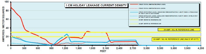
For our example pipeline application, AC modeling results show some locations to be concerned about where the 20 amps per square meter threshold is exceeded. These locations are indicated below, where the red line is above the yellow 20 amps per square meter reference line. What do we do to mitigate this risk?
In this case, we’re going to put in a gradient control line in the areas of concern next to the pipe. This is a grounding system that attaches to the pipeline so that AC being picked up by the pipeline has a place to go. The coating system is “too good” with only a few small holidays, which means all of the current being picked up tries to rush out of those few small holidays. This is how you end up with AC induced pipeline corrosion.
By putting in a grounding system at strategic locations along the pipeline, we can reduce the AC voltage being picked by discharging it and giving it a place to go.
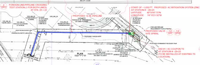
There are several ways to design an AC mitigation system but they are all basically grounding systems. Our solution in this case is shown as the blue line representing a grounding mitigation line.
Typical AC Mitigation Strategies [2:23]
Install a gradient control mat at locations where people can touch the pipeline
Maintain safe pipeline to power line separation distances to avoid arcing problems during fault conditions
If separation distances are too close, include a shield that picks up current as it is dumped to the earth and deflects away to protect the pipeline
Provide grounding of the pipe to the earth to dissipate current being picked up during steady-state conditions
What is a gradient control mat? [3:00]
A gradient control mat is a simple device that is connected to the pipeline to protect workers from step and touch potentials.
It is connected to the pipeline appurtenance where a person can touch the pipeline, and extends out enough so that somebody standing on it will not have that step and touch potential. Since it is connected to the pipeline, the entire gradient control mat has the same potential as the pipe.
As soon as I step on to that gradient control mat, I don’t have a voltage difference between me and everything else. Even if I touch the pipe, the ground below me is at the same voltage as the pipe, so no current flows through my hand, to my body and into the ground.
It is a fairly significant effort to install a gradient control mat but they protect people close to that appurtenance. Once they are above that gradient control mat, touching or being near the pipeline is not going to cause a problem. Current doesn’t flow unless there is a voltage difference. You can actually be in an environment where there is high voltage all around you, and as long as you are at the same potential (or equipotential), there is not going to be any current flow, and current is what can injure or kill you.
AC Mitigation Case Study [4:33]
In the case study shown, a pipeline runs parallel for 8 km to a transmission line, with the towers next to the pipeline. In this case the towers are too close so we use a zinc ribbon shield wire to protect from fault conditions. The zinc ribbon picks up the current and dissipates it before it can cause damage to the pipeline.
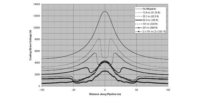
AC Mitigation Reduces Coating Stress Voltages
The chart below shows the effects without any mitigation, where you can see the voltage spike where it goes above 12000 volts of coating stress voltage.
You can see once various forms of mitigation are added, stress voltage drops below the limits. And depending on the type of coating, there’s a certain voltage limit that coating can withstand.
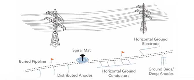
Pipeline Grounding Methods [5:46]
Spiral mat at pipeline valve stem location
Anodes in the earth that are connected to the pipeline; these become grounding rods for the pipeline
Horizontal ground conductors, connected at various lengths to the pipeline (gradient control line mitigation)
Deep anode ground beds
Deep Anode Case Study [6:25]
Deep anode ground beds are a little more expensive, however they a good solution in high resistance areas where you can’t discharge current into the ground effectively near the surface.
We did a project out west in the desert of the United States, where a new pipeline parallel to a transmission line was picking up AC voltage. In the very dry desert environment there was nowhere for this current to discharge. Grounding rods next to the pipeline do not work well in this case because the environment is so dry. We drilled holes 1000 feet into the earth and installed grounding cells. These were run up to the surface and connected to the pipeline to dissipate the AC voltage being picked up.
[7:11] There are a variety of ways to ground a pipeline; AC mitigation is basically how we ground the pipeline effectively.
AC Mitigation Materials [7:16]
The most common materials used for pipeline grounding include:
Zinc ribbon laid parallel to the pipeline
Bare copper, which is used predominantly in the corrosion industry
Engineered copper grounding systems; The MATCOR MITIGATOR® is an example of this type of system
Conducrete® systems where conductive concrete is used to enhance the earth’s surface area
AC Mitigation and Grounding Concerns [7:58]
Ease of installation
Performance
Life, how long is it going to last
Cost
Optimum AC mitigation [8:12]
The AC mitigation system is only as good as the modeling, so it is critical to ensure that modeling is accurate
Gradient control lines parallel to the pipeline are the most common grounding system used currently, although there are also quite a few locations using deep anode systems
For fault conditions, short lines at tower footings tend to be the most effective AC mitigation strategy
Have questions after viewing our AC mitigation video, or need a quote for AC mitigation materials or services? Contact us at the link below.
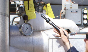
Leak Detection and Repair (LDAR) Programs are put in place to monitor process equipment leaks for fugitive emissions in the petrochemical industry. Solid LDAR programs are critical in controlling fugitive emissions of VOCs, or volatile organic compounds, that cause pollution and safety risks for facility workers and operators, and the environment.
Leak Detection and Repair (LDAR) Programs are put in place to monitor process equipment leaks for fugitive emissions in the petrochemical industry.
Maintaining refinery process equipment through an LDAR program mitigates these risks. Utilizing leak detection equipment to identify equipment leaks and then repairing those leaks in a timely manner enables operators to prevent most most fugitive emissions occurrences. In addition, successful leak detection and repair programs prevent product loss that impacts facility efficiencies and economics, the health and safety of workers, and the environment.
The article reviews fugitive emissions regulations and lays out a 5-step plan to build LDAR programs that accurately represent your project requirements.
Leak Detection and Repair Program Steps
Step 1: Develop Your Standard Operating Procedures
The first step in developing a successful leak detection and repair program is a cooperative endeavor between you and an LDAR expert to complete, approve and adopt your standard operating procedures (SOP).
Step 2: Laws Governing Your LDAR Program
In the second step, your LDAR team will research and share comprehensive knowledge of the permits, regulation(s), consolidation agreements, consent decrees, permit(s), and/or binding agreements governing your facility’s LDAR program.
Step 3: Your LDAR Unit Equipment Information Packet
In step three, your team will set up a database of regulations for each unit in your facility. The LDAR team funnels, filters, and identifies congestion overlap and applicable LDAR regulations of varying stringency into a condensed table called a Unit Equipment Information Packet. This is a comprehensive knowledge base for all who need to know more about the LDAR program on a unit-by-unit basis at the subject facility.
Step 4: Facility Process Flow Diagrams
In the fourth step, the LDAR team obtains your facility’s process flow diagrams (PFD’s), piping and instrument diagrams (P&ID’s), the P&ID abbreviations key, material balance sheets, and stream speciation data from the appropriate contact identified in your SOP in Step 1. Smart software is then utilized to highlight or color-code the P&ID’s according to stream state and service. Then the field review begins.
Step 5: Component Inventory Database and Monitoring
In the fifth step, detailed data is collected on a daily basis for affected components. The LDAR team reviews all affected components for accuracy and compliance, and perform necessary correction. All corrections are updated in the database. Monitoring commences as scheduled according to the applicable regulation set up in your LDAR Unit Equipment Information Packet in Step 2. Finally, we initiate a monthly QA/QC process to ensure ongoing compliance.
Many regulations and a lot of detailed data are involved in designing a best-in-class LDAR program to ensure regulatory compliance when it comes to fugitive emissions. It is critical to review all data reports with your facility’s operations and environmental department for understanding and acknowledgement of completion and ongoing compliance.
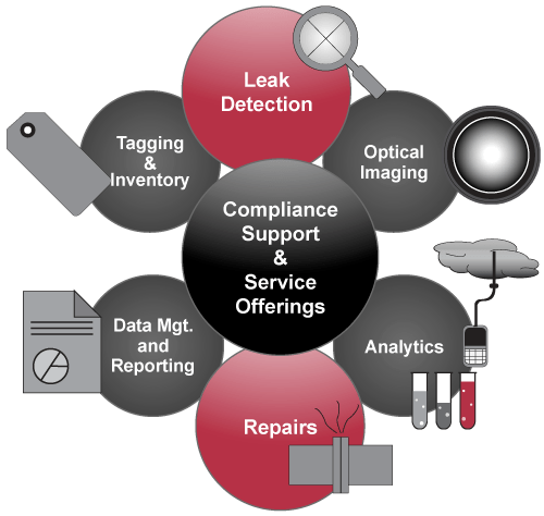
Why BrandSafway for LDAR Solutions?
BrandSafway offers 150 years of management experience, cutting-edge technology and a highly effective data management system to ensure successful LDAR programs and more, while ensuring regulatory compliance with USEPA Method 21 and other mandated requirements for VOC monitoring.
Learn about comprehensive LDAR Solutions from Brandsafway
MATCOR and BrandSafway are committed to being a valuable partner, providing a one-stop resource for industrial work solutions. By bringing together our expertise in both midstream and specialty services, we can better integrate and streamline asset and equipment management solutions for our customers in both the oil & gas and power markets.
Please click the link below to contact us if you have any questions about leak detection and repair, or if you’d like a quote for LDAR services.
Read Ted Huck’s article that appeared in the August issue of BIC Magazine, in which he addresses grid anode vs. concentric ring systems and best engineering practices for AST’s.
In this video training session we talk about AC modeling. The summary below includes video timeline indicators so you can easily find your topic of interest in the video.
In the previous AC Interference video we talked about the effects of AC interference from transmission lines on parallel pipelines. We discussed three different modes of impact:
AC Interference Recap—3 Issues (0:24)
Step and touch potential-must be below 50 volts AC
Conductive coupling where a fault condition dumps current into the earth, causing potential damage to the pipeline
AC induced voltage from the transmission lines on the pipeline
AC Modeling and Design
Best Guess Approach (0:57)
In some cases you can do a best guess AC mitigation approach, where it might not be worth the effort to put data and information into a model to determine the impact of AC interference on the pipeline.
Example: You have a simple application where you have one mile of pipeline collocated with high voltage transmission lines. You have measured that you’re picking up AC and decide that you’re going to put grounding in from point A to point B and be done with it. It is over-designed, but the cost of AC modeling would exceed the cost of this simple solution. This approach is based on experience in the field.
Complex Pipeline Arrangements Require AC Modeling (1:42)
When you get into more complex pipeline arrangements—multiple pipelines in the same corridor, multiple AC transmission lines coming in and out, multiple towers and circuits—you cannot just throw grounding in the earth and hope it is going to work. You may ground it in one location, and it may push the current somewhere else. In these cases you need to consider AC modeling.
AC Interference Modeling (2:08)
AC modeling is data intensive. And just like any model where we use a computer to predict what’s going to happen, the quality of the data impacts the quality of the results.
At MATCOR, we use a program called Right-of-Way Pro, a software package developed by Safe Engineering Services and Technology out of Canada. It is the leading AC modeling software available today. There are other packages that are less expensive and less accurate, but Right-of-Way Pro is the gold standard for AC modeling software.
AC modeling is a service that MATCOR provides. We have trained professionals with years of experience modeling AC systems in the pipeline industry, and experience with this complex software.
AC Modeling Goals (3:16)
The goals when you’re performing AC modeling are simple:
First, we calculate the fault condition stress values.
What is the worst fault condition that can occur? What is the worst that can happen at each tower and how does that affect the pipeline given the relationship of the pipeline to that tower? How far away is it? How deep is it? What is the resistance in that location? We model every tower along that collocation.
Next, we calculate induced voltage.
This is the impact of having an electrical field with the pipeline running through it and picking up voltage. We model this for every collocation. This can get rather complex when you have multiple pipelines and multiple AC towers in the same corridor.
Then, we predict the AC current density along the length of the pipeline.
In the AC Interference video we talked about AC induced corrosion being a function of how much current is being discharged off small holidays. There is a certain threshold we do not want to exceed or we will be concerned about corrosion occurring.
The model of the pipeline will show where it is picking up current. At every point along the pipeline, the model indicates, given a holiday of a certain size, whether we have a problem with AC corrosion. This will change depending on where we are along the pipeline collocation and what the soil resistivity is around the pipeline in that location. Lower soil resistivity tends to mean higher current discharge, and these tend to be the areas of concern.
Finally, we evaluate mitigation measures.
Where should we put mitigation, how much mitigation, and how effective will it be?
As we are calculating induced voltage along the length of the pipeline, we are looking for areas where we exceed 15 volts because this is a safety concern. We are also looking for areas where a 1 cm² holiday would have more than a maximum threshold of current density. 20 amps/M² is a typical threshold in the US, since that is where corrosion can occur.
AC Modeling Data Requirements (5:50)
We need a lot of data to build the model out, including data on the HVAC transmission line, the pipeline location and characteristics, and the soil resistivity. In addition, we need information about changes in the collocation relationship. These changes are called excitation points; if there is suddenly a change in the pipeline or the high voltage power line, it is often a hot spot in the system and where you will likely have problems.
HVAC Line Data (6:39)
For the HVAC line we want to know the tower geometry, which can change. How high are the towers? How long are the spans? What is the separation of the different phase conductors? AC is always a 3-phase system, with an A, B and a C line. We need to know if there are phase shifts and where they are located for the model. We also need to know the phase conductor arrangement, the conductor height and distances, if shield wire* exists, and current loading information. What is the average current flowing through that line? What is the maximum, or peak current expected? Is there anticipation that the rating will increase in the future? Finally, what are the fault and ground fault currents?
*Shield wire helps in fault conditions; if there is a fault, instead of dumping current to the earth it will travel along the shield wire.
(8:08) Collecting HVAC line data can be a challenge. It is often a combination of going out into the field and physically measuring, and contacting the power company to request information like maximum fault conditions, length of maximum fault, and how quickly will breakers trip to clear a fault. Power companies don’t always like to provide this information and will often ask operators, or consultants like MATCOR, to pay a fee. When this information is not available we sometimes make assumptions, however the more assumption we make the less valid the model becomes.
Pipeline Characteristics (9:12)
We want to know pipeline characteristics, which are generally easier to get. Either they are easier to measure or the pipeline company has good data already.
We need to know the pipeline diameter or diameters, as sometime this can change. A 16-inch pipe may become a 20-inch pipe at some location. This would be an excitation point because a change has occurred. What is the wall thickness and material? What is the coating type, thickness & quality? What is the coating conductance?
(9:52) If your pipeline has an older coating, you probably do not have a big AC problem. If you have a brand-new, high quality coating means you probably have a bigger AC problem.
Depth of cover survey—how does the pipeline change its depth relative to the earth? We need to know the accurate GPS centerline of the pipeline in addition to the location of valves, casings, bonds and foreign pipeline crossings. Finally we need to know soil resistivity at different depths and multiple locations along the pipeline. The AC modeling software has the ability to look at multiple layer effects of the soil.
All of this data must be collected and put into the model. Often the pipeline company can provide the data or we can go out and measure it.
AC Modeling Software Key Features (11:35)
Up to five layers of soil resistivity modeling
A large conductor database—including most transmission line conductors, all copper conductors and mitigation devices such as zinc ribbon and the MATCOR MITIGATOR®
The ability to model large networks with multiple pipelines and multiple power lines along a corridor in the same model
AC Modeling Costs (12:11)
For a relatively simple collocation, you may not need to perform AC Modeling. A very simple AC modeling job might be $20,000. The cost can be well over $100,000 for a project requiring a lot of data collection and modeling effort.
In some cases it may be simpler to put in $10,000 worth of grounding and “overdesign” the AC mitigation system since the cost of modeling would be greater. In other cases, AC modeling is an absolute necessity.
AC Modeling Software Capabilities (12:42)
(13:17) This is an example of AC modeling with multiple high voltage transmission lines and a pipeline going from one location out to a terminal. We have to model each of those transmission lines as well as the pipeline characteristics
Transformers, insulators, substations and other devices
Different phasing, pipe diameters and coating type configurations in one model
Solid state decoupler sizing
3-D viewing and plotting
AC corrosion output
Fault modeling
AC Modeling Software Output (13:42)
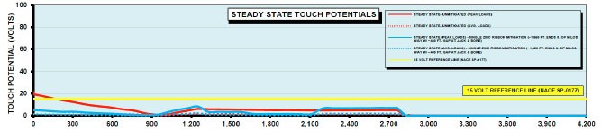
The output from the software shows you along the length of the pipeline, those areas where you have concerns about steady state touch potentials, from a safety standpoint where it might be above 15 volts.
AC Modeling Software – Touch Potentials
It will also provide your 1 cm holiday leakage current density, indicating areas where you are at risk for AC induced corrosion.
AC Modeling Software – Current Density
In addition the software provides areas where fault currents can exceed the maximum allowable for your coating stress.
When is AC Modeling Not Required? (14:16)
Simple applications
When overdesigning AC mitigation solves the problem
In our next segment we will talk about AC mitigation. What do you do once you know where the problems are?
Have questions after viewing our AC modeling video, or need a quote for AC modeling? Contact us at the link below.

 It also serves as a foundational input to cathodic protection design, helping engineers develop systems based on accurate field data.