Overall
The US Pipeline regulatory environment is poised to see several new rules implemented to expand the scope and effectiveness of pipeline regulations with a goal to improve the integrity and safety of hazardous material pipeline. These rule changes were all initiated years ago and have been winding their way through the regulatory process, soliciting input from the industry and from concerned citizens, environmental groups and other interested parties.
The Liquids “Final Rule”
In January of 2017 in the last few days of the Obama Administration, the Department of Transportation’s Pipeline and Hazardous Materials Safety Administration issued a final rule amending its Rule 49 CFR 195 that among other things expanded integrity management and leak detections beyond high consequence areas (HCA’s). The Final Rule tightened standards and broadened data collection and monitoring requirements for pipeline operators. A few days into the Trump administration, the White House issued a directive to federal agencies to freeze sending new regulations to the Office of the Federal Register (OFR) and withdrawing any regulations sent to the OFR. Thus the liquids “Final Rule” that was 6 years in the making was withdrawn and is awaiting resubmittal by the new administration.
While the exact requirements of the Final Rule may be changed, some of the key changes from the withdrawn rule included:
• Assessment of non-HCA pipeline segments every 10 years in compliance with provisions of 49 CFR Part 195.
• Increased use of inline inspection tools for all hazardous pipelines in HCA.
• Requirement for leak detection systems for covered pipelines in both HCA and non-HCAs.
PHMSA anticipates coming out with their revised “Final Rule” in the Fall of 2018.
The Gas “Mega Rule”
On the gas side of the pipeline regulatory environment, 49 CFR Parts 191 and 192, several public meetings have been held regarding PHMSA’s proposed gas rules, often referred to as the Gas Mega Rule. The rulemaking changes originally recommended would have nearly doubled the current number of pages in the regulations. PHMSA has announced that instead of one Mega Rule, the effort would be broken into three separate rules that are expected to be introduced in 2018 and to go into effect in 2019. Part 1 addresses the expansion of risk assessment and MAOP requirements to include areas in non-High Consequence Areas (HCAs) and moderate consequence areas (MCAs.) Part 2 of the rule making focuses on the expansions of integrity management program regulations including corrosion control to gathering lines and other previously non-regulated lines. Part 3 of the gas rule making is expected to focus on reporting requirements, safety regulations and definitions to include expanding into related gas facilities associated with pipeline systems.
Technological advances in horizontal drilling and fracking have changed the oil and gas production landscape that propels the US Pipeline industry. This combined with an increasing demand for natural gas and the promise of larger export markets for both LNG and US crude oil have led to a surge in new pipeline construction. As a result, pipeline corrosion prevention, including cathodic protection design and engineering expertise is critical as the industry adapts to a changing production landscape and new distribution challenges.
Cathodic Protection Engineering Capabilities
MATCOR has been heavily involved in several key engineering projects including pipeline cathodic protection design for new transmission stations. Whether these are compressor stations for gas pipelines or pump stations for liquids pipelines, pipeline owners appreciate MATCOR’s innovative application of linear anodes when designing new construction stations.
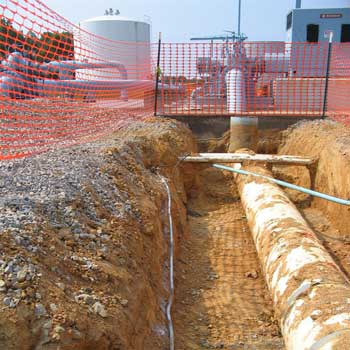
Pipeline Cathodic Protection Design with Linear Anodes
The advantages of using linear anodes in a new pipeline station environment include:
Installation in the same trench as the buried piping during initial construction greatly reduces installation costs
Close coupling of the anode to the piping greatly minimizes the current losses of the CP system to the station’s grounding system
Utilizes a low anode gradient / low current output anode system that minimizes interference concerns with other structures and with foreign pipelines outside the station area
Provides exceptionally long anode life using MMO (mixed metal oxide) anodes operating at mA/ft current output.
MATCOR has successfully pioneered the use of linear anodes in plant environments for two decades. With the recent surge of pipeline projects, the use of linear anodes in stations has gained significant traction in the market. MATCOR design engineers and field technical personnel are uniquely qualified to perform engineering, pipeline cathodic protection design, field installation support, commissioning and testing services for these critical infrastructure projects.
MATCOR also offers a full suite of cathodic protection design and AC mitigation design services for transmission pipeline and oil and gas production pipeline gathering systems.
Have questions or need a quote for engineering and design or materials for your pipeline cathodic protection system? Contact us at the link below.
We appreciate the question: “How does soil resistivity impact current rating.” The short answer is that resistance has nothing to do with anode rating. Here is a more detailed response:
Anode current rating – all anodes have a current rating based on how long they can be expected to operate at a given current rating. All anodes have some defined expected life based on current output and time – so many Amp-Hours of service life. For example a magnesium anode may have an expected consumption rate of 17 lb/Amp-year (7.8 kg/amp) so if a 17 lb anode is operated at 0.1 amps it would have a life of 10 years. For MMO anodes, they too have an expected life. For our linear anode rated at 51 mA/m it is important to know that that rating is actually 51 mA/m for 25 years. So a 100m anode segment with this rating would have an expected life of 127.5 Amp-years. If this anode were operated at 5.1 amps (full rated capacity) it would be expected to operate for 25 years. IF it were operated at 2.55 amps (50% of rated capacity) it should last 50 years. The anode life is generally linear. Please note that resistance has nothing to do with the anode current rating – the anode current rating merely calculates the life of the anode as a function of how many amps for how long of time.
Actual current output – just because you install an anode rated for 5.1 amps for 25 years (our 100m segment of 51 mA/m SPL-FBR) does not mean that the anode will output this amount of current. It just means that at that current rating you can expect 25 years of life. The anode is merely one component of the overall cathodic protection circuit. The actual output of the anode is function of Ohms Law ( Voltage = Current * Resistance). It would make sense to note that if the system Voltage were zero (the rectifier were turned off or disconnected) then the anode would not have any current output. Likewise if the 100m anode segment were installed in a very low resistance environment and driven by a powerful rectifier, the current could be much higher than 5.1 amps which would result in a much shorter life.
Why anode rating is important to the CP designer – the CP designer is tasked with protecting a specific structure for a given period of time (protect this pipeline for 30 years.) The CP designer then calculates, based on actual testing or established guidelines, the amount of current that should be sufficient to achieve appropriate CP levels to protect the structure. This results in an answer of some number X of amps required. If the requirements are to protect the structure for Y number of years, then the anode life required is X * Y (# of amps times # of years). This defines the minimum amount of anode life that is needed.
The next question the CP designer must address, once it is determined how much current is needed, is how to design a system that will generate that amount of current. Since Ohms Law dictates that Voltage = Current * Resistance (V=IR) then if we know that the Current = Voltage/Resistance (I=V/R.) Thus the CP designer must understand how to calculate system resistance (R) and must provide sufficient driving force (V) Several factors affect system resistance (R) including anode geometry – the longer an anode, the lower its resistance – which in many applications is a big benefit to the linear anode. One of the great benefits of the linear anode is that because of its length, in most applications the soil resistivity plays a lesser role since the anode resistance to earth is generally low for a wide range of soil resistivities due to its length. For extremely high resistance environments, linear anodes may be the best option since short anodes will not have a low enough resistance.
There are other factors that go into CP design including current distribution and making sure sufficient current is being applied across the entire structure.
CP Design can be very complicated. I hope that the above explanation is helpful, but if there is a specific application to evaluate, please contact us with the details. We are also available, for a reasonable engineering fee, to develop and/or review CP system designs.
Chalfont, PA (April 2018) – MATCOR, Inc., the trusted full-service provider of proprietary cathodic protection products, systems, services and corrosion engineering solutions announces that senior engineer and pipeline practice lead Jeffrey L. Didas has been elected to the position of president for NACE International (NACE), the Worldwide Corrosion Authority. His term as president is one year commencing at the close of the NACE Corrosion Conference & Expo 2018, taking place April 15-19 in Phoenix, Arizona.
Jeffrey L. Didas will serve a one-year term as NACE president commencing at the close of the NACE Corrosion Conference & Expo 2018
As NACE president, Didas will advise, govern, oversee policy and direction, and assist with the leadership and promotion of NACE International to support the organization’s mission. He will also serve as chairman of the executive committee and an officer of the association. His responsibilities will include presiding at all official functions of the board of directors and executive committee, including the annual membership meeting of the association and the annual NACE banquet. This position is part of Didas’ five-year commitment to NACE following previous roles as vice president elect and vice president. Following his term as president he will serve one year as past president and one year on the nominating committee.
“I look forward to serving NACE as president over the next year,” said Didas. “My focus will be on member engagement, retention and benefits, moving forward with the strategic plan and our vision for NACE 2030, and promoting the groundbreaking corrosion industry IMPACT Study.”
Didas, an industry expert sought worldwide and active NACE member since 1975, has 44 years of diverse corrosion experience working for pipeline and energy company owner-operators and most recently for MATCOR.
Prior to his executive leadership roles, Didas held a variety of national NACE positions including:
Treasurer of NACE International, the NACE Foundation and the NACE Institute
Director of the Member Activities Committee – MAC
Committee chair for several technical exchange groups (TEGs), including the Corrosion Control Coordinating Committee (TEG 022X), Pipeline Crossings: Steel-Cased, Thrust-Bored, and HDD TEG 208X) and Steel-Cased Pipelines (TG 012)
Technology coordinator for technology management group TMG C1 – Corrosion Prevention and Control for Concrete, Land Transportation and Coating Technology
Vice chair of the NACE Institute Policy & Practices Committee
Member of the Technical Practices Committee – TPC/Technical Coordination Committee – TCC since 1978
He has also served as chair, vice-chair, and general member of several administrative committees over the past 44 years.
Didas received the NACE Brannon Award in 2014 and the NACE Distinguished Service Award in 2001 for his many contributions to the organization. He also received the Appalachian Underground Corrosion Short Course (AUCSC) Colonel Cox award in 2010.
Didas holds the highest level of NACE certification as a Corrosion Specialist and a number of other NACE certifications, including Cathodic Protection Specialist, Coatings Specialist, Chemical Treatment Specialist, Senior Corrosion Technologist, Corrosion Technologist, Corrosion Technician and Level 3 Certified Corrosion Inspector. In addition he is a SSPC (Society for Protective Coatings) certified Protective Coatings Specialist.
Didas graduated from Thomas A. Edison State University in Trenton, NJ, with a BSET in Electrical Engineering. He acquired his ASEE in Electronics Technology from Springfield Technical Community College in Springfield MA.
About NACE
NACE International, The Worldwide Corrosion Authority, serves nearly 36,000+ members in 130 countries and is recognized globally as the premier authority for corrosion control solutions. The organization offers technical training and certification programs, conferences, industry standards, reports, publications, technical journals, government relations activities and more. NACE International is headquartered in Houston, Texas, with offices in San Diego, California; Kuala Lumpur, Malaysia; Shanghai, China, Sao Paulo, Brazil and Al-Khobar, Saudi Arabia.
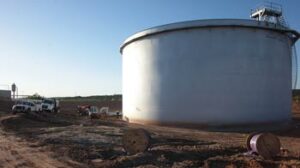
This program applies to replacement cathodic protection systems for above ground storage tank (AST) bottoms.
Tank Emergency? Contact Us About Our Quick Ship Cathodic Protection for Tanks Program
With existing ASTs, you may not always have the luxury of a planned tank bottom cathodic protection system replacement. After taking a storage tank out of service for inspection, you are often required to make an immediate decision as to the integrity of the existing floor. In some cases, this means a new floor has to be quickly planned and installed to minimize the time that the tank is out of service.
MATCOR Quick Ship Cathodic Protection for Tanks Program
MATCOR is pleased to announce our stock tank bottom anode system to meet your replacement needs with very short notice.
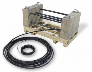
For your tank bottom replacement applications where a very fast delivery is required, MATCOR will now be maintaining stock of our Tank Ring Anode System.
Up to 200 ft diameter SPL-FBR tank ring anodes
Pre-assembled and ready to ship from our Chalfont PA facility
Two day turnaround
Set up in concentric rings with five foot spacing
Requires a minimum of just 6 inches of sand cover from the new tank bottom
Designed for 25 mA/ft output which is generally sufficient for 50+ year anode life based on a nominal current density of 2 ma/ft2 of surface area.
For more information please contact your MATCOR sales representative or contact us at the link below.
Have questions or need a quote for a replacement tank bottom cathodic protection system? Contact us at the link below.
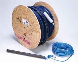
The Durammo Deep Anode System is the only complete, factory assembled, ready to install deep anode system available. Here are the top 9 reasons it outperforms conventional deep anodes.
1. FACTORY ASSEMBLED RELIABILITY
Durammo® Deep Anode System
The Durammo deep anode system is factory assembled, tested and shipped ready to install. With a conventional High Silicon Cast Iron or Graphite deep anode system design, the installer has to make sure he has all of the anodes, that each anode has the appropriate individual cable length, that he has all of the vent pipe segments, the couplings for the vent pipe assemblies, the centralizers, a junction box, etc… With Durammo it is simply a matter of attaching the weight shipped with the system to the anode system nose cone and lowering the factory assembled complete system in place.
2. CONTINUOUS DEEP ANODE PERFORMANCE
The Durammo design utilizes a single continuous wire anode assembly. With conventional deep anode systems, multiple individual anodes (as many as 20 in some cases) are lowered into the deep anode borehole and spaced a nominal distance apart. The use of a continuous anode configuration eliminates the mutual anode interference issues that cause different anodes inside the borehole to operate at different current outputs. The result of having different individual anodes each operating at differing outputs is that over time the various individual anodes have vastly different consumption patterns and the anode system’s stability changes as individual anodes start to fail while other anodes may hardly be operating at all.
3. LONGER OPERATING LIFE
Conventional deep anode system utilizes high silicon cast iron or graphite anodes that have large (macro) consumption rates measured in pounds/amp year whereas mixed metal oxide (MMO) anodes are dimensionally stable and have very low (micro) consumption rates measured in micrograms/amp-year. This means that the normal 15-20 year life that is typical of many conventional deep anode systems can be replaced with 30+ year life Durammo systems, often with a lower installed cost.
4. LOWER COST OF OWNERSHIP
Typically the Durammo deep anode system costs less than a comparable conventional deep anode system, offers a longer design life and provides for a more stable performance –these factors combined results in a lower total cost of ownership. While the savings will vary depending on the specific deep anode system requirements, as a general rule the more conventional anodes being used, the greater the overall cost savings of using the Durammo deep anode system.
5. EASE OF INSTALLATION
Durammo Deep Anode System Installation
The ease of installation of the Durammo deep anode system is one of the most impressive features that this product offers. Once the anode borehole has been drilled, a typical Durammo deep anode system can be lowered into place in less than two minutes. This is only part of the installation story; however, as the time saved, while impressive, is not the only benefit of an easy installation. Just as critical is the positive impact that the slim profile continuous wire anode design’s ease of installation has on system reliability. As a continuous anode system with a slim profile single assembly to lower down the hole, there is minimal risk of damage to the anode system cabling during installation. Contrast that to the installation consecutively of numerous large diameter conventional anodes one on top of the other. The risk of cable damage to lower anodes increases with each subsequent anode.
6. LIGHT WEIGHT/ EASE OF HANDLING
The Durammo deep anode assembly weighs significantly less than a comparable conventional anodes system and takes up much less space when placed on a wooden skid – for multiple deep anode installations, two anode assemblies can be stacked on a single skid to further reduce space and facilitate handling. The lower weight reduces transportation costs and makes it easier to install when compared to heavy individual anodes that are bulky and must be manually lifted into place before lowering. The Durammo system is also much more robust and is not subject to breakage during transportation and handling. This is not the case with high silicon cast iron or graphite anodes, both of which are subject to breaking.
7. BETTER COKE COLUMN & LOWER RESISTANCE
Several factors play an important role in determining the resistance of a deep anode system. The coke column plays a critical role in the anode system resistance (as does the soil layering, the available moisture and the environment around the deep anode system.) Dwight’s equation is often used to predict anode system resistance with the assumption that the entire coke column is one single anode. Thus the quality of the coke column and the ability of current to flow freely up and down the coke column are important in reaching the resistance values predicted using Dwight’s Equation. Durammo’s continuous anode design eliminates the mutual anode interference affects that impede current flow up and down the coke column and the significantly reduced space taken up by the wire anode system helps assure a better coke column formation and freer current flow. The end result is often a reduction in anode system resistance over a comparable conventional anode system.
8. SUPERVENT™ TECHNOLOGY
Chlorine gas generation can cause premature failure of a deep anode system’s cabling. Even chlorine resistant Kynar® cabling, which is standard with all Durammo systems, is subject to failure in the event of chlorine gas pocketing. Systems that utilize standard, non-chlorine resistant, cabling are even more at risk in the event that salts are present in the soil allowing chlorine gas formation. MATCOR’s SuperVent pipe has ten times more open surface area than the standard All-Vent pipe that is common in the industry. With ten times more open surface area, the venting effectiveness is 100 times better as pressure drop is a function of the square of the open surface area. Better venting translates into longer operating life.
9. KYNEX® CONNECTION TECHNOLOGY
The Durammo anode system is available with Kynex injection molded wire to anode cable connection technology. This patent pending technology provides for a fully automated connection that offers the highest quality of waterproof connections. Historically, premature mixed metal oxide anode failures have occurred because of poor cable selection or faulty anode connections. MATCOR’s use of high quality dual extruded HMWPE/Kynar cabling with Kynex connection technology assures outstanding system reliability.
Have questions or need a quote for a deep anode system? Contact us at the link below.
In June 2017, MATCOR’s parent company Brand Energy and Infrastructural Services joined forces with Safway Group to form one even greater company – BrandSafway – providing world class services to industrial, commercial and infrastructure companies through 350 locations in 30 countries. In January 2018, BrandSafway announced the formation of the “Integrity Services Group”, combining Midstream/MATCOR, LDAR and Industrial Specialty Services into one powerful group of over 500 employees, each uniquely qualified to supply our customers with safe, integrated and high-performing asset management and protection services, as well as regulatory compliance solutions.
What is the impact of AC interference on pipelines?
This 16-minute AC interference video training course reviews the 3 basic effects of AC interference on pipelines, including:
15-volt safety threshold
Fault conditions
AC induced corrosion
The summary below includes video timeline indicators so you can easily find your topic of interest in the video.
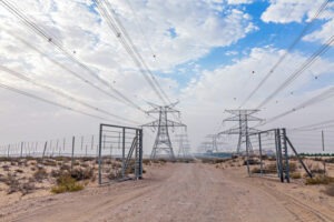
What is AC Interference?
(0:25*) AC interference is an interaction that occurs between high voltage power lines and pipelines in a common utility corridor.
*References the time in the AC Interference Video where this topic is reviewed.
1. Fault Condition Interaction Modes
In the video, our AC mitigation expert Ted Huck explains fault currents and two modes of interaction with pipelines, conductive coupling and stress voltage.
Conductive Coupling
(1:09) Conductive Coupling is a relatively rare occurrence when there is a fault condition along the power transmission line and a large amount of electricity is dumped to the earth. The collocated pipeline is subject to this discharge of electricity through arcing, defined as the flow of current through the soil. Although rare, conductive coupling can burn a hole through the pipeline and cause a catastrophic failure.
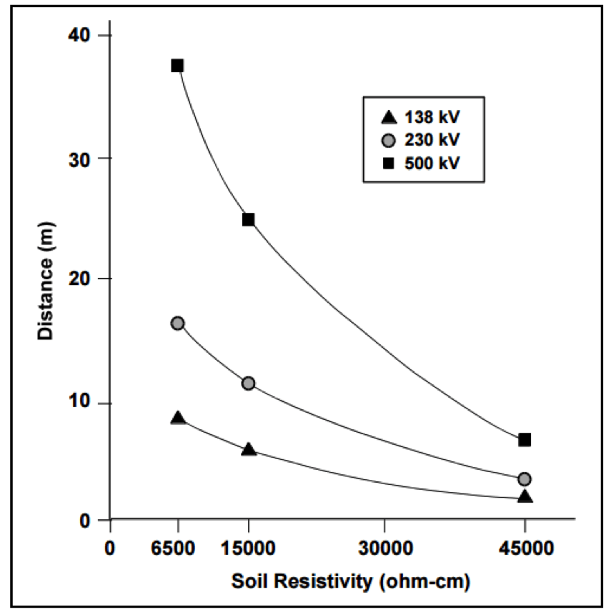
Determining the Safe Distance from Tower to Pipeline for Arcing
(2:08 in the AC Interference video) Arcing depends on soil resistivity and voltage.
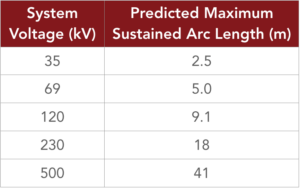
Arc Length
(2:49) We can predict how far arcing can occur through the soil by measuring soil resistivity and system voltage.
(2:16) In this segment, our AC mitigation expert describes a real customer case scenario where arcing caused catastrophic failure of a gas pipeline.
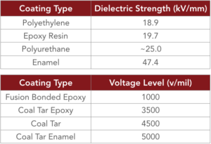
(4:01) Another issue that can occur with conductive coupling is a voltage rise radiating out from the location where the electricity is dumped to the earth. Newer pipeline coatings cannot handle excessive voltage stress.
Stress Voltage
(4:41) Exceeding maximum voltage stress can damage the pipeline coating.
Electromagnetic Induction
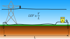
(5:44) Electromagnetic Induction is a steady state occurrence where current flowing through the line creates an induced current flowing in the opposite direction along the parallel pipeline. If the pipeline is close enough to the power transmission line, and runs parallel to it for some length, it will be in the electromagnetic field that exists around the AC transmission system. Being in that electromagnetic field, it will inductively pick up current throughout the longitudinal electrical field.
Longitudinal Electrical Field (LEF)
(6:56) The LEF field can be measured by running a copper cable along the pipeline and measuring the current.
2. AC Induced Corrosion
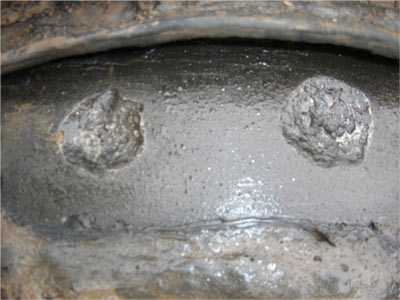
(7:26) AC induced corrosion occurs when alternating current is picked up by the pipeline that cannot effectively dissipate back to the earth. Well coated pipelines have very few places for the current to exit the pipeline and are at risk for significant, rapid AC-induced corrosion. Older coating systems have many defects, or natural grounding points enabling AC on the pipeline to naturally dissipate, so AC corrosion is a relatively new concern. With newer coatings, AC current continues to build until it finds a small coating holiday (typically 1-3 cm2) to exit the pipeline, risking catastrophic failure.
(9:00) AC induced corrosion on a pipeline appears as round craters in the pipeline coating.
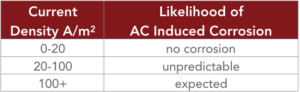
How likely is AC-induced corrosion to occur?
(9:43) We can determine the likelihood of AC induced corrosion based on the current density.
Current Density Formula
(10:05) This formula shows how to calculate current density for a given holiday size; our example is based on a holiday surface area of 1cm².
In our example, 4.4 volts AC is all it takes to cause pipeline coating damage. With older pipeline coatings that threshold is in the 15 volts AC range.
100 A/m² Threshold – When Will Pipeline Coating Damage Due to AC Interference Occur?
(11:37) This chart shows holiday size and AC voltage required to exceed the 100 A/m² AC-induced corrosion threshold at varying soil resistivity.
Refer to NACE Report 35110, AC Corrosion State-of-the-Art: Corrosion Rate, Mechanism, and Mitigation Requirements for additional information about the 100 A/m2 threshold.
In Europe, refer to standard BS EN 15280:2013, evaluation of induced current damage likelihood of buried pipelines applicable to cathodically protected pipelines.
The Relationship Between AC Induced Corrosion and Cathodic Protection
(12:00)
No cathodic protection – high likelihood of pipeline corrosion due to AC influence
Excessive CP current, or over polarization may increase AC-related corrosion risk
(12:50) Pipelines have above ground appurtenances such as valve stems and test stations that are subject to the AC currents picked up by the pipeline. These can pose a serious safety risk to workers, including shock or death. These risks are referred to as step and touch potential.
Touch Potential is defined as current flowing from touching an electrified device, through the body and down to the earth.
(13:38) Step and touch potential can cause serious safety risks, including injury or death. A maximum of 15 volts is the industry standard threshold for safety.
Step Potential can occur even without the worker touching the electrified device. In this case, current can flow up one foot, through the body and back down to the earth through the other foot, potentially causing serious injury or worse.
Refer to NACE SP0177-2014 (formerly RP0177), Mitigation of Alternating Current and Lightning Effects on Metallic Structures and Corrosion Control Systems, Paragraph 5.2.1.1 for additional information on the 15 volt safety criteria.
Summary
This AC interference video reviews the 3 basic effects of AC interference on pipelines, including the maximum 15 volt safety threshold—how much voltage can accumulate on the pipeline before it becomes a safety hazard to a person touching the pipeline? If there is more than 15 volts AC, we must do something to drop that voltage. Then there are rare but potentially catastrophic fault conditions, or the dumping of current to the earth. Finally there is AC induced corrosion, a result of the interaction of the electromagnetic field generated by current flowing through the lines and how it reacts with the pipeline. Pipeline operators must be prepared to mitigate these risks.
Have questions after viewing our AC interference video, or need a quote to mitigate the risks of AC interference? Contact us at the link below.
AC Modeling enables pipeline operators to evaluate and plan for mitigating AC corrosion.
There continues to be much greater awareness by pipeline owners and regulators of the adverse interactions (AC Interference) that can occur between buried pipelines and above ground high voltage AC transmission systems that share some parallelism in a common right of way. When AC Interference conditions exist, it is important that the potential impact is evaluated and when necessary mitigated. For many applications, the most cost-effective approach to assess and mitigate the impact of AC Interference is to use a complicated computer AC modeling program.
The term AC Modeling really covers multiple modeling evaluations, as an AC corridor can often be quite complex. They may include multiple HVAC transmission systems and multiple pipelines in a common corridor or multiple shared right of ways along a long length of pipeline. Each may require its own AC modeling. In addition, the modeling looks at several different risks assessing how the pipeline is affected by steady state AC induced current, the impact of fault current along the pipeline and an evaluation of the impact of a fault current on above ground appurtenances to assure safe operation in accordance with IEEE std. 80 step and touch potential criteria.
Thus, it is very important for any successful AC modeling effort that the modeling software be of an extremely high quality and capable of properly handling the complex interactions of these various networks. The engineer or technician developing the model must also have sufficient experience and expertise to properly configure and operate the model, and evaluate the results.
AC modeling involves four key phases:
Data Collection
Creating the Model
Establishing criteria
Evaluating mitigation strategies
Data Collection
The data collection is critical to a successful modeling effort (the old adage garbage in = garbage out is quite applicable for these projects). The data requirements can be broadly broken out into three categories:
The characteristics of the AC Transmission Line(s)
Physical geometry data on the tower including GPS location, height, # of AC circuits, tower configuration, height of each conductor, lowest point of each conductor, separation distance between conductors, shielding wire type and location, location of any phase transpositions, etc…
Electrical data on the Transmission Line(s), including peak and average AC Load (in each direction), fault current max and duration.
The characteristics of the Pipeline(s)
GPS location, depth of cover, coating type, coating resistance, pipeline diameter, pipeline wall thickness, location of all above ground appurtenances, location of all CP test stations and bonds to foreign structures.
The characteristics of the Environment
Detailed soil data at multiple depths along the length of the pipeline, location of any crossings, presence/location of any foreign CP Stations or other interference conditions.
Collecting all the appropriate data often requires some field studies and working with both the pipeline owner(s) and the transmission line operator to get the required data. In some cases, the modeler cannot get all the required information and must make an educated guess – the accuracy of which can affect the quality of the results.
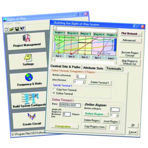
Creating the Model
AC modeling software enables input of pipeline, transmission and environmental characteristics
Once all the data is collected, the modeler creates the model space, detailing all the pipelines and HVAC systems and providing the requisite parameters associated with each of these elements. There are several commercially available AC modeling software packages that each have their own format for inputting the pipeline, transmission and environmental characteristics. Once the model has been built, it can take hours, days and in some cases weeks, of processing time to run simulations and for the model to provide the results of the simulation.
Evaluating the Model Results Against Established Criteria
The results of the initial model run need to be evaluated against the criteria that is established by the pipeline owner. In the absence of specific guidance from the owner, MATCOR’s default criteria are:
No more than 20 A/m2 AC current density for mitigating AC corrosion during steady state induced AC current
3000 volts maximum coating stress during fault conditions for newer FBE type coated pipelines in accordance with NACE standard SP0177-2014
15 VAC for step and touch potentials at above ground appurtenances
For any given application, one or more of these criteria may be exceeded along the model’s area of analysis.
Adding AC Mitigation and Reevaluating the Modeling Results
Once the initial unmitigated results have been evaluated against the criteria that has been established, the modeler then adds, based on their experience with these systems, a mitigation scheme to the model with grounding at selected locations. This is often an iterative project where the model is run and the results evaluated and then if necessary, additional mitigation can be added or excess mitigation can be removed and the model rerun again in search of an “optimized” modeling solution that addresses all of the threats and results in meeting the requisite criteria.
Final Report
Once the AC modeling effort has developed a solution, the modeler develops a final report. Typical components of a final report include an introduction detailing the scope of the study, graphical illustrations of the pipeline(s) and transmission line(s) overlaid onto a satellite image, description of the modeling software used, detailed graphs/charts showing the results of the modeling, detailed drawings and bill of materials for the AC mitigation solution being recommended and appendices with the underlaying data.
Summary
AC Interference issues can be quite complex and modeling often offers the only valid way to assess and mitigate the risks from AC faults and steady state induced currents. When considering AC modeling it is important to look at the model being used and the modeler performing the evaluation.
Learn about our AC modeling and mitigation solutions:
Marine environments can be some of the harshest environments on the planet for corrosion of steel structures. Indeed, the earliest application of cathodic protection can be traced back to Sir Humphrey Davy and the British Navy’s investigation into corrosion on copper sheathed wooden vessels. This video demonstrates MATCOR’s impressed current sled anodes that are successfully being used to protect steel piles for jetties, docks and other similar steel structures in marine environments.
At 1:03 in the video, we demonstrate how the marine anode sled operates with a trade show model.
Sea-Bottom™ Anode Marine Sled Anode
At 4:05 you see a MATCOR Sea-Bottom Marine Anode Sled being lowered into the water as part of the cathodic protection system protecting a steel jetty structure in Indonesia. The jetty is constructed with four interior rows of concrete piles and an exterior row of 247 bare metallic piles. The operator initially considered galvanic anodes to protect the jetty from corrosion – until they compared the cost, time and effort to install the required 374 aluminum anodes each weighing 200 each. Instead they opted for six marine anode sleds, taking only three days to install.
For assistance with near shore marine anode systems, please CONTACT US.
Cathodic Protection Systems | Cathodic Protection Design | alternatives to sacrificial anodes and galvanic anodes
 Installation in the same trench as the buried piping during initial construction greatly reduces installation costs
 In June 2017, MATCOR’s parent company Brand Energy and Infrastructural Services joined forces with Safway Group to form one even greater company – BrandSafway – providing world class services to industrial, commercial and infrastructure companies through 350 locations in 30 countries. In January 2018, BrandSafway announced the formation of the “Integrity Services Group”, combining Midstream/MATCOR, LDAR and Industrial Specialty Services into one powerful group of over 500 employees, each uniquely qualified to supply our customers with safe, integrated and high-performing asset management and protection services, as well as regulatory compliance solutions.