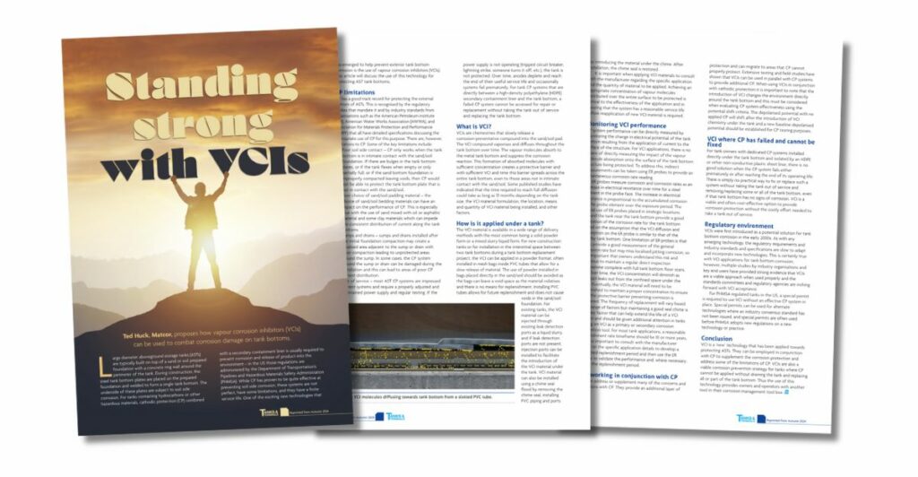
In the Autumn 2024 edition of Tanks & Terminals magazine, MATCOR’s Ted Huck highlights an alternative to traditional corrosion prevention methods for aboveground storage tanks (ASTs): Vapour Corrosion Inhibitors (VCIs).
ASTs, especially those storing hazardous materials like hydrocarbons, are highly susceptible to corrosion on their steel tank bottoms. Typically built on sand or soil foundations with a concrete ring wall, these tanks are vulnerable to soil-side corrosion over time.
While cathodic protection (CP), often combined with a secondary containment liner, has been a standard solution to prevent leaks and environmental damage, it has limitations. VCIs are a newer technology that offers an additional layer of protection for external tank bottoms, addressing some of the challenges CP alone cannot solve.
To get in touch with our team of experts for more information, to ask a question, or to get a quote, please click below. We will respond by phone or email within 24 hours. For immediate assistance, please call +1-215-348-2974.
BrandSafway seminars provide you with in-depth knowledge and practical skills across a wide range of topics. Each seminar includes a 1-hour educational session, a tour, and lunch. MATCOR-specific seminars offer specialized training in cathodic protection and rectifier management:
Cathodic Protection 101: An introduction to cathodic protection, its principles, techniques, and its application in preventing corrosion. This seminar is perfect for those new to the field or looking to refresh their knowledge on preventing corrosion in various structures.
Rectifier School: Comprehensive training on rectifier operation, maintenance, and troubleshooting for effective cathodic protection systems. This seminar is ideal for corrosion technicians responsible for impressed current rectifiers.
AC Interference and Mitigation: A detailed introduction to AC interference and mitigation for engineers and corrosion professionals, focused on practical theory and solutions.
For a full list of BrandSafway’s technical seminars, click here.
To request a lunch and learn seminar, please email matcorsales@matcor.comor call Lisa Porter at 215-327-3002.
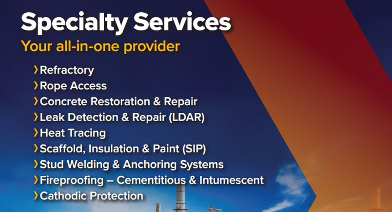
BrandSafway’s Specialty Services
At BrandSafway, we pride ourselves on being the leader in industrial specialty services, offering unparalleled expertise and the largest fleet of scaffolding and access equipment in North America. In addition, MATCOR maintains the largest fleet of construction equipment for cathodic protection projects. Whether your project is large or small, our innovative solutions and dedicated team are here to ensure you meet any challenge safely and efficiently.
As part of BrandSafway, MATCOR specializes in providing advanced corrosion protection, including cathodic protection and AC mitigation solutions. Explore our brochure to learn about how BrandSafway and MATCOR can support your unique needs with industry-leading services and equipment.
For more information, to ask a question, or schedule a seminar, please contact our team of corrosion experts. We will respond by phone or email within 24 hours. For immediate assistance, please call +1-215-348-2974.
The Appalachian Underground Corrosion Short Course (AUCSC) stands as a cornerstone of corrosion protection education, and this year’s event promises to be nothing short of exceptional. The 69th annual gathering, on May 7-9, 2024, is expected to welcome over 1,200 attendees, offering a comprehensive three-day exploration from the fundamentals to advanced knowledge in corrosion mitigation strategies.
Insights from Geoff Rhodes
Geoff Rhodes is the Proposal Manager and a CP field engineer at MATCOR, as well as a dedicated member of the AUCSC General Committee who has invaluable insights into the event. Geoff’s journey with AUCSC began in 2003 as a student, evolving into a pivotal role as a General Committee member in 2004. Over the years, he has transitioned from a student to an instructor, demonstrating a steadfast commitment to advancing the knowledge base within the corrosion protection community.
Contributions to AUCSC
With a wealth of experience under his belt, Rhodes has served as the sub-chair for both the Basic and Technology Today tracks, ensuring the seamless execution of instructional content and the alignment of topics with industry trends.
His contributions have been instrumental in shaping the educational landscape of AUCSC, fostering an environment conducive to learning and professional growth.
Diverse Cathodic Protection Curriculum
The AUCSC curriculum caters to a diverse audience, offering programming tailored to both non-technical individuals and seasoned field technicians and engineers. Attendees can delve into a myriad of topics, ranging from coatings and pipeline integrity management to specialized techniques such as laser ablation of coatings and internal corrosion mitigation.
Outdoor workshops further enrich the learning experience, providing hands-on exposure to cutting-edge corrosion prevention technologies and methodologies.
Expo Highlights
Beyond the classroom, the event features an expo with over 100 vendors, offering attendees the chance to explore the latest products and services in the corrosion protection industry. This convergence of education and networking opportunities makes AUCSC a must-attend event for professionals seeking to stay abreast of the latest developments in cathodic protection and related disciplines.
Rhodes’ Reflections
Reflecting on his tenure with AUCSC, Rhodes emphasizes the profound impact of the event on his professional journey, including staying abreast of trends and networking with peers. His sentiment is echoed by industry stalwarts like George Krewson, a former AUCSC Chairman, who says, “If I had to recommend just one conference for industry education each year, AUCSC would be it.”
Rhodes’ Expertise and MATCOR
Geoff Rhodes’ extensive experience as a participant and contributor to AUCSC underscores the event’s significance within the corrosion protection community. As MATCOR’s proposal manager and field engineer, Rhodes continues to leverage his expertise to drive innovation and excellence in corrosion mitigation strategies. With certifications from AMPP for CP Technologist and Internal Corrosion Technologist, Rhodes exemplifies the commitment to continuous learning and professional development embodied by AUCSC.
Corrosion Protection Education
In summary, the Appalachian Underground Corrosion Short Course is a beacon of excellence in corrosion protection education. Year after year, it remains a vital platform for knowledge exchange, collaboration, and professional advancement—a testament to the enduring legacy of committed industry veterans like Geoff Rhodes.
One of the specialty groups in the BrandSafway Specialty Services Division is Diamond Thermal Systems (DTS), an esteemed leader in reliability and safety. DTS specializes in the evaluation, repair, and long-term care of heat trace systems.
DTS offers customized services to evaluate risks, identify vulnerabilities, and offer comprehensive heat tracing solutions.
What is Heat Tracing?
Heat tracing maintains consistent processing temperatures and protects pipelines and equipment from the adverse effects of cold environments. It is a reliable solution in industrial settings where precise temperature control is crucial for operational efficiency and equipment integrity.
Heat tracing is crucial for safeguarding assets and maximizing productivity across various industries, including oil and gas, chemical plants, and power generation.
The Importance of Heat Trace System Audits
Conducting thorough heat trace audits is the best defense against winter freeze-ups. It reduces the need for costly emergency repairs and promotes proactive system reliability.
DTS heat trace audits comprehensively delve into the critical components of your heat trace system:
Power Distribution Panels
Power Junction Boxes and Heat Trace Cables
Insulation Systems
Post-audit, you’ll receive a comprehensive report detailing system insights, accompanied by visual documentation, findings, and actionable recommendations. Moreover, we provide transparent pricing for turnkey services encompassing heat tracing, insulation, and scaffold services required for any necessary repairs.
Supporting All Heat Trace Systems
At DTS, they proudly support all heat trace systems, regardless of the original equipment manufacturer (OEM). Our commitment to excellence means that irrespective of your system’s specifications, we possess the expertise and resources to deliver optimal solutions.
Your MATCOR representative can help put you in touch with the right contacts at our sister company, DTS, should you have any questions or are looking for heat tracing help.
To get in touch with our team of experts for more information, to ask a question, or to get a quote, please click below. We will respond by phone or email within 24 hours. For immediate assistance, please call +1-215-348-2974.
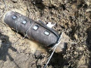
Recently, at the AMPP Association for Materials Protection and Performance Big Sky Section meeting, MATCOR’s Ted Huck presented a case study featuring the casing repair of a high-pressure natural gas pipeline running under railroad tracks and feeding into a power plant.
Following the repair, a vapor corrosion inhibitor (VCI) is installed to prevent corrosion.
Click on the presentation below to check out the development of a casing repair with VCI project scope, removing the short, sealing the casing, and installation of the VCI product through the vent pipe.
To get in touch with our team of cathodic protection and AC mitigation experts for more information, to ask a question, or get a quote, please click below. We will respond by phone or email within 24 hours. For immediate assistance, please call +1-215-348-2974.
In a recent MATCOR blog post, we discussed exothermic welding and pin brazing: Cathodic Protection Pipeline Connections: Exothermic Welding vs. Pin Brazing.
While the article focused on informing, we briefly discussed safety: “both methods are safe procedures when trained personnel follow the correct procedures.” This article will take a deeper dive into the safety considerations and procedures around making connections to pipelines using exothermic welding and pin brazing technologies.
Trained Personnel
Only trained personnel with sufficient experience should make connections to a pipeline. Therefore, short-service and inexperienced personnel should only perform this work if doing so under the direct supervision of an experienced person.
Daily Tailgate Safety Meeting
Note: Different organizations use different terminology, but the basic process is the same.
Every day the team plans and reviews various site activities. At this meeting, they review all applicable instructions, and identify, discuss, and document all potential safety hazards. Each team member signs the document to verify that they understand all safety concerns and their responsibilities.
Safety Hazards
Because pipeline connections are thermal, potential safety issues include flash, burns, accidental ignition, pipe burn-through, pipeline damage, inhalation risks (dust, smoke, ignition product, etc.), and eye injuries.
Therefore, safe entry conditions must exist before team members enter a pipeline or other structure excavation site.
Proper PPE
Personal Protective Equipment (PPE) is non-negotiable when performing pipeline connection work. All team members must:
Wear a hard hat and face shield to protect their head and face.
Wear safety glasses under their face shield with a 5.0 shade rating for pin brazing to protect the eyes.
Wear a particulate mask to protect yourself from grinding dust entering the lungs. Additional breathing protection equipment may be required to protect against inhalation of welding fumes in poorly ventilated areas.
Wear fire-resistant clothing to protect the torso, arms, and legs.
Wear leather gloves free of flammable or thin material to protect the hands.
Wear safety-toed leather boots (no rubber, neoprene, or other flammable materials) to protect the feet.
Positive Identification of the Pipeline
Before any physical work such as excavation, coating removal, heating, grinding, or welding on a pipeline or other structure, the project owner should approve the proposed work and work methods. This step includes positive identification of the pipeline or other asset(s) by the owner or owner’s representative.
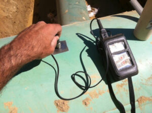
Air Monitoring
It is critical to monitor the air at the work site both initially and continually during the work with an LEL gas sensor.
Before proceeding, also test all flanged fittings and valves within 25 feet of the pipeline connection location should be tested with the gas sensor.
Thickness Measurement
Another critical safety step is for trained personnel to test the ultrasonic thickness of the area to be welded. The goal of this testing is to confirm that adequate wall thickness is present to prevent weld “burn-through.”
The table below details the minimum steel wall thicknesses as recommended by ERICO.
Record all results and compare them to nominal wall thickness. If the results indicate possible wall loss due to internal corrosion, the team must not proceed with exothermal welding.
Note: Do not perform exothermic welding if you measure a difference of 20% or more from nominal thickness or readings below 0.110” are measured.
Nominal Pipe Size
Schedule
Wall Thickness
0.5″
40
0.109″
0.75″
40
0.113″
1-2″
10
0.109″
2.5-4″
10
0.112″
5-10″
5
0.109″
10+”
5
> 0.109″
Coating Removal and Surface Profiling
Before coating removal, the pipeline operator should confirm that the coating is asbestos-free. Alternative removal procedures and safety precautions are required if the coating contains asbestos. A face shield should be used whenever grinding activities are performed.
Additional Considerations and Precautions
Explosive Internal Conditions
For active gas and liquids pipelines, the fluid velocity and lack of oxygen prevent the internal fluid from igniting due to the temperature rise in the pipeline wall. However, out-of-service lines are likely not fully purged, and oxygen and vapor may ignite inside the pipeline or vessel; purge these lines before proceeding.
Only perform exothermic welding on standard-thickness steel piping or vessels. Aluminum, copper, and thin-walled steel pose a greater risk of burn-through.
Don’t use anything larger than a 15-gram charge when welding onto steel fuel piping or vessels. Other structures, such as ductile iron pipes, may be more tolerant of more significant weld charges.
As you can see, both methods of pipeline connections are safe. However, adequately trained and experienced people must use the proper procedures and take the appropriate precautions.
To get in touch with our team of cathodic protection and AC mitigation experts for more information, to ask a question, or get a quote, please click below. We will respond by phone or email within 24 hours. For immediate assistance, please call +1-215-348-2974.
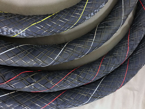
In February 2020, MATCOR revamped our SPL-FBR Linear Anode Product Line Offerings and introduced color coding for easy identification of different product ratings. Furthermore, MATCOR eliminated the 16 mA/ft, 50 mA/ft, 150 mA/ft, and 250 mA/ft from our standard offering. All of our SPL-FBR anode ratings are based on a 25-year continuous operation. The output ranges available are color-coded using different tracer wire coloring as shown in the chart below:
SPL-FBR Linear Anode Color Coding
CURRENT OUTPUT RATING
COLOR CODE
25 mA/ft
Yellow
100 mA/ft
White
200 mA/ft
Red
400 mA/ft
White and Red
MATCOR continues to offer, for specific projects or applications, custom anode output ratings on an as-needed basis.
MATCOR continues to be the world’s leading manufacturer of linear anode products, utilizing our patented Kynex® connection technology. With our product color coding, it is easier for our clients to identify the current output of their linear anodes.
To get in touch with our team of cathodic protection and AC mitigation experts for more information, to ask a question, or get a quote, please click below. We will respond by phone or email within 24 hours. For immediate assistance, please call +1-215-348-2974.
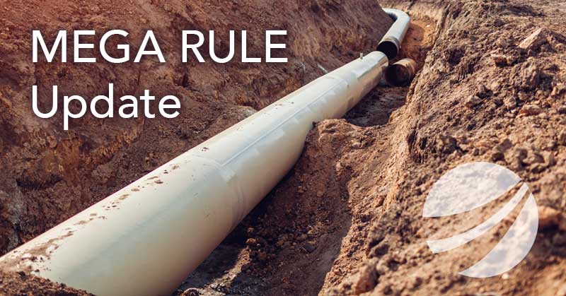
Recently PHMSA issued its final rule expanding Federal pipeline safety oversight to all onshore gas gathering pipelines. Known as the PHMSA Mega Rule, this ruling has tremendous impact on the US pipeline industry, adding significant scope to the current pipeline integrity management requirements.
The final rule affects tens of thousands of miles of previously unregulated gas gathering pipelines. Also, pipeline operators have to report safety information for more than 450,000 miles of gas gathering lines governed by Federal reporting requirements.
Some of the impacts of the PHMSA MEGA rule on the industry include:
An approximately 20% increase in the number of regulated pipelines in the United States The addition of 20% more regulated pipelines had a significant impact on an industry where highly qualified integrity professionals and related services were limited in supply and the industry was already struggling to meet demand. These additional pipelines required significant integrity resources.
Expedited reporting requirements The time restrictions for implementing the new rule were accelerated, with initial reporting requirements having started in July 2020. The time to comply with these regulations was reduced by 20% from the initial draft order timeline.
Increased cathodic protection requirements Many pipelines that previously were not regulated and have not had proper CP required a properly designed, maintained, and tested cathodic protection system.
What Does The Final Rule State?
The final rule expands PHMSA’s Part 192 to gas gathering lines that fall within Class C, a new pipe category. Within Class C, the requirements for operators vary based on a risk scale. The risk scale varies with pipeline diameter and proximity to people (BIHO – buildings intended for human occupancy).
For pipelines that meet these criteria, the requirements for corrosion control (CFR 49 Part 192 Subpart I – Requirements for Corrosion Control) will now apply to these previously unregulated lines. The Part 191 incident and annual reporting requirements have expanded to include all previously uncontrolled gas gathering lines, regardless of Class.
How Can MATCOR Help Company Operators Comply with PHMSA Mega Rule?
Gas producers and midstream gas pipeline operators have to reevaluate their pipeline networks to incorporate any previously uncontrolled pipelines to comply with CFR 191 and CF 192. MATCOR offers a wide range of cathodic protection and integrity services to help our customers including:
If you are looking for help complying with the PHMSA’s new Mega Rule and its additional requirements, please contact us. We will respond by phone or email within 24 hours. For immediate assistance, please call +1-215-348-2974.
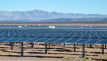
The US is constructing an increasing number of very large solar power generation farms, which brings about the question–what about corrosion? This new article explores solar farmsteel pile corrosion. Do the buried galvanized steel piles supporting solar arrays meet service life requirements?
Galvanized steel pile corrosion can occur in as little as five years.
Big Footprint
We continue to construct an increasing number of solar power generation facilities. The United States plans even more as it continues to pursue policies encouraging renewable energy development.
The economies of scale make these facilities more competitive with other electrical generation technologies. These utility-scale solar farms have a capacity of anywhere from 1 MW to 1000+ MW. One feature of these solar farms is their physical footprint. The average solar farm requires 6-8 acres of land to support the tens of thousands of PV cells necessary to generate electricity at this scale.
For example, the Mammoth Solar Farm project in northern Indiana, once completed, will have a generation capacity of 1650 MW. And it will cover an area of 13,000 acres and use more than 2.85 million solar panels. This is the largest project in the US and should become fully operational in 2024.
Steel Piles That support Solar Arrays: What About Corrosion?
Given these facilities’ size, cost, and anticipated service life, a fair question to ask during the design phase is: what about corrosion? Specifically, the buried support structures that hold the solar arrays in place.
Typically, construction crews drive or screw galvanized steel piles into the soil to support the solar panels’ frames. Galvanized steel piles generally have a good service life in most environments for this application. However, as with all steel structures, they are subject to corrosion. Eventually, steel pile corrosion will adversely affect the support structure’s integrity.
Therefore, solar farm operators should consider the impact of corrosion on the service life of the galvanized piles during the project’s design phase.
Start with The Piling Details
The first step in the corrosion assessment process is to know your piles.
Any sizable solar farm project will require thousands of steel piles. The type of pile and the galvanizing thickness significantly impacting the project cost.
Unfortunately, structural engineers often do not consider corrosion when sizing the piles. They are keenly aware of loading concerns and select the pile to use based on a detailed soil load-bearing analysis and wind load analysis. They consider how big and how deep the piles need to be to support the predicted mechanical loads. This is often the only consideration. As a result, any conversation regarding corrosion is often relegated to – don’t worry, the piles are galvanized.
How Corrosive is the Environment?
But even galvanized piles are subject to corrosion, and in a highly corrosive environment, that service life might be much lower than expected. Therefore, additional corrosion mitigation measures, such as cathodic protection, might be warranted in some cases.
Given the massive footprint covering hundreds to thousands of acres these sites require, a thorough corrosion assessment for the entire area is warranted.
Typically, Geotech firms are contracted early in the project to perform detailed soil testing across these sites. This testing provides the requisite soil load capacity data to design the structural supports properly. While performing the site-wide testing, these firms will often perform some representative soil resistivity testing. While these sample soil resistivity tests may indicate the soil’s corrosiveness, they are often insufficient to evaluate correctly.
MATCOR Study: A Soil Testing Analysis
In one study performed by MATCOR, a comprehensive soil testing analysis found that much of a solar farm was in moderately corrosive soils. Still, a significant part of the facility was in very corrosive soils. In addition, the service life calculations varied significantly for the piles depending on their location within the solar farm. Estimated life ranged from 17 years to 30+ years.
Another factor in the service life calculations is the anticipated degradation of the piles during installations. The impact on the zinc coating can vary significantly depending on the soil characteristics.
Steel Pile Corrosion: How Long Will the Steel Piling Last?
The first phase of the service life of driven steel piles is the outer zinc layer of the galvanized steel pile. Zinc acts as both a coating and a galvanic anode. As the zinc layer is consumed, the underlying steel substrate is exposed. Therefore, the estimated service life, in simple terms, is the anticipated service life of the zinc coating plus the expected service life of the steel substrate.
We define the service life for solar structural galvanized steel piles as some allowable percentage thickness loss before compromising the pile’s integrity.
There are a lot of factors that affect the pile’s corrosion rate, including:
Presence of copper grounding bonded to the pile
Degradation of the zinc coating during the driving of the pile
Differential soil resistivity strata
Differential oxygen levels/aeration
Location of the water table in the area of buried piles
One of the biggest drivers of accelerated corrosion for piles is the presence of copper grounding. When steel piles are connected to a copper grounding grid, their service life can be significantly reduced as the zinc coating layer and the underlying steel substrate act as galvanic anodes. This can be very impactful in low soil resistivity environments.
Significant Steel Pile Corrosion Can Occur in as Little as Five Years
In some extreme cases, corrosion of the galvanized piles can be structurally significant in less than five years of service. In most cases, the service life in corrosive environments can be anywhere from 10-25 years of service. A service life of more than 50 years in low-corrosivity soils might be achievable.
Solar farms are a growing part of our electrical generation portfolio and will continue to see substantial investments in the next several decades. Given the footprint and cost of these facilities, design engineers should seek corrosion assessments from qualified corrosion engineering firms such as MATCOR to confirm that the piling systems used to support the solar arrays meet the facilities’ service life requirements.
If you need assistance with galvanized steel pile corrosion protection, please contact us. We will respond by phone or email within 24 hours. For immediate assistance, please call +1-215-348-2974.
 In February 2020, MATCOR revamped our